
Hazardous waste incinerator with dry cooling slag discharging mechanism

A dry cooling and incinerator technology, applied in incinerators, combustion methods, combustion types, etc., can solve problems such as increasing heat consumption load and production cost, ineffective utilization of ash and slag heat, and increasing water treatment difficulty and load. , to achieve the effect of strengthening heat exchange, reducing emissions and reducing heat loss

Active Publication Date: 2018-11-16
EAST CHINA ENG SCI & TECH
View PDF9 Cites 1 Cited by
  • Summary
  • Abstract
  • Description
  • Claims
  • Application Information

AI Technical Summary

Problems solved by technology

Although the cooling efficiency is relatively high, due to the use of cooling water for contact cooling, the heat of ash and slag has not been effectively utilized, and waste water will be generated during the slag discharge process, which increases the difficulty and load of water treatment. , and the fluctuation of the water surface during the feeding process will inevitably produce unorganized waste gas, which will cause energy loss and double pollution of waste water and waste gas, resulting in environmental pollution
In the situation of increasingly stringent environmental protection standards, the heat consumption load and production cost of the project have been virtually increased

Method used


Image

  • Hazardous waste incinerator with dry cooling slag discharging mechanism
  • Hazardous waste incinerator with dry cooling slag discharging mechanism
  • Hazardous waste incinerator with dry cooling slag discharging mechanism

Examples


Embodiment Construction

[0024] In order to make the objectives, technical solutions, and advantages of the present invention clearer, the following further describes the present invention in detail with reference to the accompanying drawings and embodiments. It should be understood that the specific embodiments described herein are only used to explain the present invention, and not to limit the present invention.

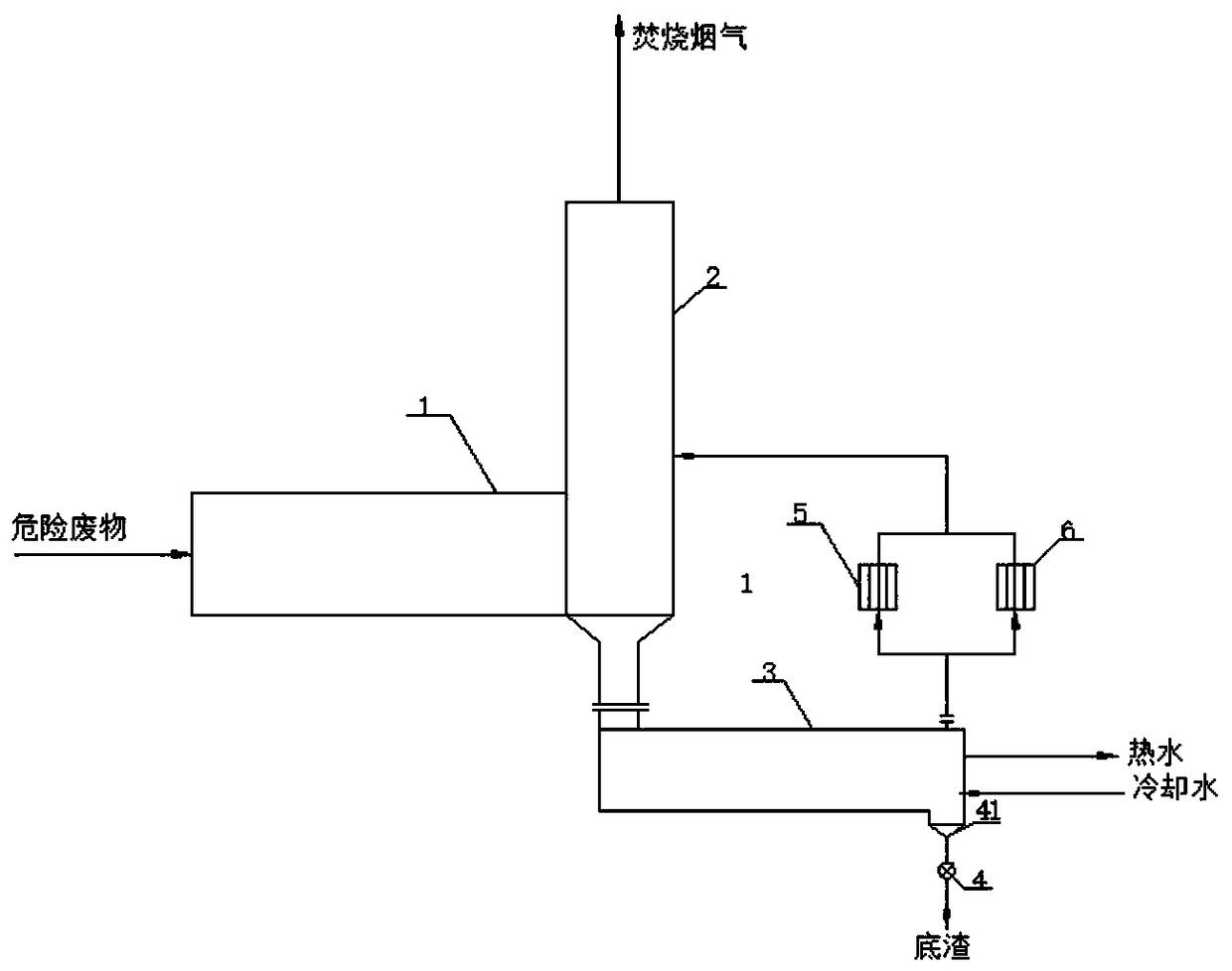
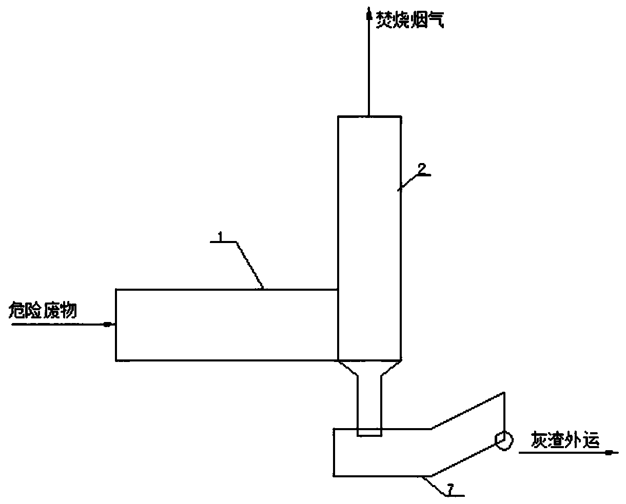
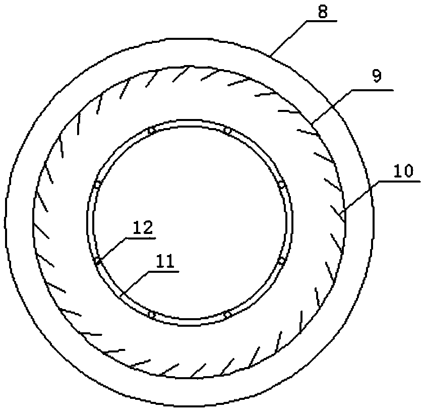
[0025] It includes a rotary kiln 1, a second combustion chamber 2 and a slag discharging mechanism arranged in series. One end of the rotary kiln 1 is a hazardous waste inlet, and the other end is connected to the lower inlet of the second combustion chamber 2. The top of the second combustion chamber 2 is For the flue gas outlet, the bottom of the second combustion chamber 2 is connected to a slag discharging mechanism through a downcomer. The slag discharging mechanism includes an ash cooling device 3 and a filter device. The ash cooling device 3 includes a coaxially arranged housing 8 And...


PUM


Abstract

The invention relates to the technical field of hazardous waste disposal, in particular to a hazardous waste incinerator with a dry cooling slag discharging mechanism. The hazardous waste incineratorcomprises a rotary kiln, a secondary combustion chamber and a slag discharging mechanism which are arranged in series; the slag discharging mechanism comprises ash slag cooling equipment and a filtering device; the ash slag cooling equipment comprises a shell and a roller which are coaxially arranged, one axial end of the roller is connected with a driving motor through a connecting shaft, and rotation of the roller relative to the shell is achieved; a circular-ring-shaped water pipe is coaxially arranged in one end of the roller; and a cooling water pipe is coaxially arranged in the roller and symmetrically provided with water pipe fins arranged along a pipe body. According to the hazardous waste incinerator with the dry cooling slag discharging mechanism, reverse-flow indirect contact heat exchange is achieved, and the condition that in the prior art, water source pollution is caused by direct contact heat exchange is changed; and meanwhile, roller fins and the water pipe fins can significantly increase the heat transfer area and can better conduct ash slag heat, the roller fins and the water pipe fins are arranged regularly and achieve a guiding effect on ash slag discharging, and the energy efficiency of the disposal system is improved.

Description

Technical field [0001] The invention relates to the technical field of hazardous waste disposal, in particular to a hazardous waste incinerator with a dry cooling and slagging mechanism. Background technique [0002] Hazardous waste is one of the important pollution sources that endanger the human ecological environment and human health. In recent years, with the development of society, the amount of its generation has also increased significantly. If it is not effectively disposed of, it is discharged at will, not only to the water environment, air environment and soil The serious impact and damage caused by the environment will also pose a direct threat to personal safety and health. Therefore, the harmless disposal of hazardous waste is a social issue that must be paid attention to. [0003] Hazardous waste incineration is a typical technical solution for hazardous waste treatment and disposal. It is also the most effective and thorough disposal method for combustible solid wast...

Claims


Application Information

Patent Timeline
Patent Type & Authority Applications(China)
IPC IPC(8): F23G7/00F23J1/00F28D11/02
CPCF23G7/00F23J1/00F28D11/02
Inventor 龚幸张铭王争刚陈岗汪炎
Owner EAST CHINA ENG SCI & TECH
Learn More