Method for detecting pose of mobile magnetic source

A pose and magnetic source technology, applied in the size/direction of the magnetic field, measuring device, electromagnetic measuring device, etc., can solve the problem of large errors in the detection results of the moving magnetic source, so as to facilitate analytical calculation and improve pose detection. Accuracy and efficiency improvement

Active Publication Date: 2018-11-16
BEIJING INSTITUTE OF TECHNOLOGYGY
View PDF5 Cites 15 Cited by
  • Summary
  • Abstract
  • Description
  • Claims
  • Application Information

AI Technical Summary

Problems solved by technology

However, the magnetic field signal obtained by the magnetic sensor includes a large proportion of the driving magnetic field signal and the effective magnetic source signal. If the background magnetic field cannot be accurately removed, the detection result of the moving magnetic source will inevitably have a large error.

Method used


Image

  • Method for detecting pose of mobile magnetic source
  • Method for detecting pose of mobile magnetic source
  • Method for detecting pose of mobile magnetic source

Examples


Embodiment 1

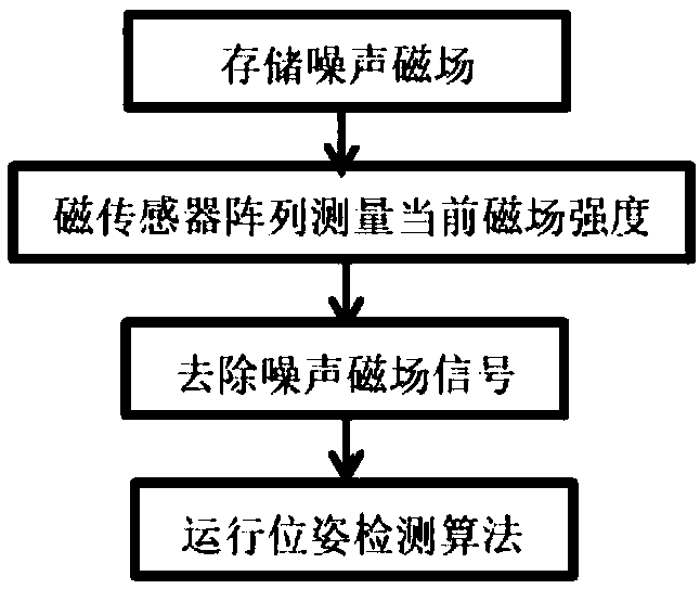
[0032] Step 1, storing the noise magnetic field.

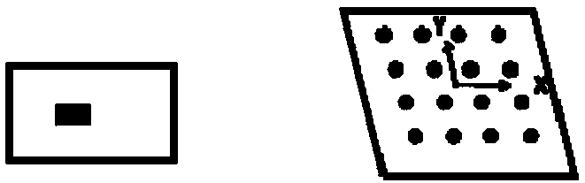
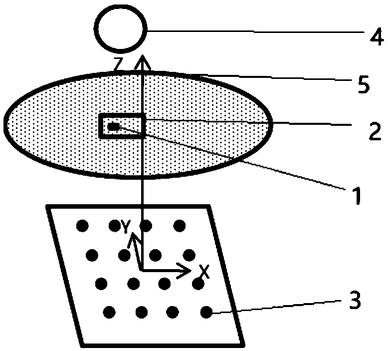
[0033] In the absence of the magnet 1 to be tested, move the driving magnet 4 so that the driving magnet 4 has different positions and attitudes relative to the magnetic sensor array, and store the magnetic field strengths at different positions and attitudes of the driving magnetic field as the magnetic field strength of the noise magnetic field. like Figure 4 As shown, the array coordinate system is established with the center of the magnetic sensor array as the origin, the plane where the magnetic sensor array is located is the XY plane, the direction perpendicular to the XY plane is the Z direction, and the coordinates of the center of the array are (0,0,0). Set the driving magnet 4 With respect to the fixed N poses of the magnetic sensor array, N≥1, place the driving magnet 4 in any position, stop moving, and maintain the pose. Record the coordinates of these N poses in the array coordinate system, set as (x 1n ,y 1n ...

Embodiment 2

[0042] Example two such as Figure 5 As shown, the difference from Embodiment 1 is that when storing the noise magnetic field in step 1, the pose density of the driving magnet 4 is different, and it is necessary to ensure that the magnetic field strength is between x, y, The difference in each direction of z is less than the specified threshold, and this density can be obtained by experiment. The selection of the specified threshold is related to the final required positioning accuracy. When the position accuracy of the required detection result is within 10mm and the attitude accuracy is within 5 degrees, the magnetic field difference between any adjacent storage position and attitude in the x, y, and z directions is not greater than 100-300mGs.

[0043] In step 2, the difference is that if the current pose of the driving magnet 4 has not been stored in advance, then two pre-stored poses that are closer to the current pose of the drive magnet than other stored poses are judg...


PUM


Abstract

The invention provides a method for detecting the pose of a mobile magnetic source. Adopted equipment comprises a driving magnet, a magnetic sensor and a controller. The method includes steps: a magnetic field intensity of the driving magnet relative to the magnetic sensor with different poses is pre-stored as a noise magnetic field; the driving magnet drives a to-be-detected mobile magnetic source to move to a certain pose, and the controller determines a magnetic field intensity of a current noise magnetic field according to a relation between a current pose of the driving magnet and the pre-stored poses of the driving magnet; and measuring a total magnetic field intensity of the to-be-detected mobile magnetic source with the current pose by employing the magnetic sensor, obtaining the magnetic field intensity of the mobile magnetic source through difference of the total magnetic field intensity and the magnetic field intensity of the current noise magnetic field, and obtaining the pose of the current mobile magnetic source through calculation according to the magnetic field intensity of the mobile magnetic source. According to the method, high-precision magnetic field signals ofthe mobile magnetic source can be obtained, and the pose detection precision is improved.

Description

technical field [0001] The invention relates to the technical field of magnetic field strength, in particular to a method for detecting the pose of a moving magnetic source. Background technique [0002] Traditional colonoscopy uses a colonoscope to operate. The doctor uses external force to control the colonoscope to enter the colon. When turning in the intestinal tract, it is easy to touch the upper wall, which increases the pain of the patient. Therefore, the technology of capsule endoscopy has been developed accordingly. The capsule endoscope currently used has small magnets inside the capsule, and an external magnet is used to guide the capsule. [0003] External magnet-guided endoscopic capsules have obvious advantages, including a large range of motion, higher detection coverage, and the ability to complete detection and treatment at designated locations. [0004] In the detection process, it is necessary to locate the position and posture of the capsule, and its pos...

Claims


Application Information

Patent Timeline
Patent Type & Authority Applications(China)
IPC IPC(8): G01B7/00G01R33/02A61B1/04
CPCA61B1/041G01B7/00G01B7/003G01R33/02
Inventor 李敬周基阳黄强周龙吴磊徐磊
Owner BEIJING INSTITUTE OF TECHNOLOGYGY
Why Eureka
Try Eureka