Joint measurement method based on laser radar and binocular visible light camera

A technology of laser radar and measurement method, which is applied in the direction of measurement device, radio wave measurement system, photogrammetry/video measurement, etc., and can solve the problems of grid coordinate errors, bad results, errors, etc.

Active Publication Date: 2018-11-16
XI'AN INST OF OPTICS & FINE MECHANICS - CHINESE ACAD OF SCI
View PDF3 Cites 79 Cited by
  • Summary
  • Abstract
  • Description
  • Claims
  • Application Information

AI Technical Summary

Problems solved by technology

[0009] 2) It is easy to introduce cumulative errors, and the accuracy is not guaranteed
The fitting process of the three planes must have errors, which will lead to the introduction of errors in the solution of the intersection points of the three planes, and then the calculated other grid coordinates will have errors
The results obtained by such methods are often not good, because the dependent calibration points need to be very large, and the calibration data must be optimized to obtain good calibration values
[0010] 3) As many grid points as possible should be used in the calibration to reduce the error, because the three-dimensional target has three sides, in order to allow the camera to capture as many grid points as possible, there are requirements for the placement of the target, if placed randomly, the captured The layout of the grid points in the image is irregular, and it is difficult to automatically complete the matching between the 3D grid points and the grid points of the 2D image. If there are too many points, manual intervention is very troublesome.

Method used


Image

  • Joint measurement method based on laser radar and binocular visible light camera
  • Joint measurement method based on laser radar and binocular visible light camera
  • Joint measurement method based on laser radar and binocular visible light camera

Examples


Embodiment Construction

[0090] The present invention will be described in detail below in conjunction with the accompanying drawings and specific embodiments.

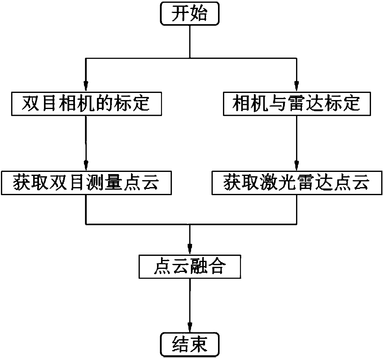
[0091] In the measurement system built in this embodiment, the laser radar is set up in the middle of the binocular camera, the overall coordinate system of the binocular camera measurement system is established on the left camera, the origin is established at the optical center, the u direction of the camera imaging plane is the X direction, v The direction is the Y direction, and the optical axis direction is the Z-axis direction.

[0092] The camera used in the measurement system is Jinghang JHSM300f. The pixel size is 3.2*3.2μm, and the resolution is 2048*1536. Two sets can be placed freely to form a binocular measurement system.

[0093] The lidar uses FARO Focus3D X330 HDR, which is a high-speed 3D scanner with an ultra-long scanning distance. The scanning range is 0.6-330 meters; the measurement error is ±2mm at 10m and 25m; the ref...


PUM


Abstract

The invention provides a joint measurement method based on a laser radar and a binocular visible light camera to obtain accurate and dense three-dimensional information simply and efficiently. The joint measurement method comprises assuming that the laser radar is a camera device with a fixed internal reference; directly projecting three-dimensional point cloud data into a two-dimensional image, calculating rotation and translation relationships between the laser radar device and the binocular camera by using an image processing method and the matching between the two-dimensional images; creatively introducing an idea for obtaining a matrix norm and a matrix trace to solve a rotation matrix; finally fusing laser radar and binocular stereo vision point cloud data. The method not only can obtain an accurate position and attitude information, but also can reconstruct the special texture and feature information of a target surface, which has a high application value for spacecraft dockingand hostile satellite capture in the military field and workpiece measurement and unmanned driving in the civilian field.

Description

technical field [0001] The invention belongs to the technical field of radar and visual measurement, and relates to a method for measuring three-dimensional information. Background technique [0002] Binocular vision mainly studies how to use computers to realize the functions of human eyes, that is, to use two-dimensional projection images to realize the perception, recognition and understanding of three-dimensional scenes in the objective world. With the rapid development of computer technology, people have more and more demands on 3D models. The working principle of binocular stereo vision measurement is to shoot a scene with two cameras in different positions, and obtain the three-dimensional coordinate value of the point according to the parallax of the spatial point in the two images. [0003] After long-term development of the visual measurement system, many advanced image processing methods have emerged. But vision systems can still only be used in engineering envi...

Claims


Application Information

Patent Timeline
Patent Type & Authority Applications(China)
IPC IPC(8): G01S17/02G01S17/06G01S7/40G01C11/00G01C25/00
CPCG01C11/00G01C25/00G01S7/40G01S17/06G01S17/86G01C11/36
Inventor 曹剑中胡国良周祚峰郭惠楠黄会敏
Owner XI'AN INST OF OPTICS & FINE MECHANICS - CHINESE ACAD OF SCI
Why Eureka
Try Eureka