Wall-flow preventing spray tower

A technology of spray tower and tower body, applied in the field of air purification equipment, can solve the problems of decreasing mass transfer efficiency, more consumption, increasing the height of spray tower, etc., so as to reduce production cost, fully and uniformly react, and improve practicability Effect

Inactive Publication Date: 2018-11-20
SHENZHEN LEILING GUANGTONG TECH DEV CO LTD
View PDF5 Cites 7 Cited by
  • Summary
  • Abstract
  • Description
  • Claims
  • Application Information

AI Technical Summary

Problems solved by technology

When the liquid flows downward along the packing layer, wall flow phenomenon sometimes occurs. The wall flow effect causes the gas-liquid two-phase distribution in the packing layer to be uneven, thereby reducing the mass transfer efficiency. Therefore, the packing layer in the spray tower is usually It is divided into two sections, and a redistribution device is installed in the middle. After redistribution, it is sprayed on the lower packing. However, this increases the height of the spray tower and increases the construction cost of the equipment. Not only that, but the lower packing will still The phenomenon of wall flow cannot guarantee that the problem of uneven distribution of the gas-liquid two-phase in the packing layer can be solved. Moreover, with the increase of the spray tower, the water pump needs to consume more energy to pump the solution in the bottom water tank to a higher place. Moreover, the position of the filler in the filler layer is fixed, and the air is easy to react with the solution at the filler in some positions, while other positions lack contact with the air, resulting in uneven distribution of the reaction in the filler layer, thereby reducing the existing The practicality of the spray tower

Method used


Image

  • Wall-flow preventing spray tower
  • Wall-flow preventing spray tower
  • Wall-flow preventing spray tower

Examples


Embodiment Construction

[0025] The present invention is described in further detail now in conjunction with accompanying drawing. These drawings are all simplified schematic diagrams, which only illustrate the basic structure of the present invention in a schematic manner, so they only show the configurations related to the present invention.

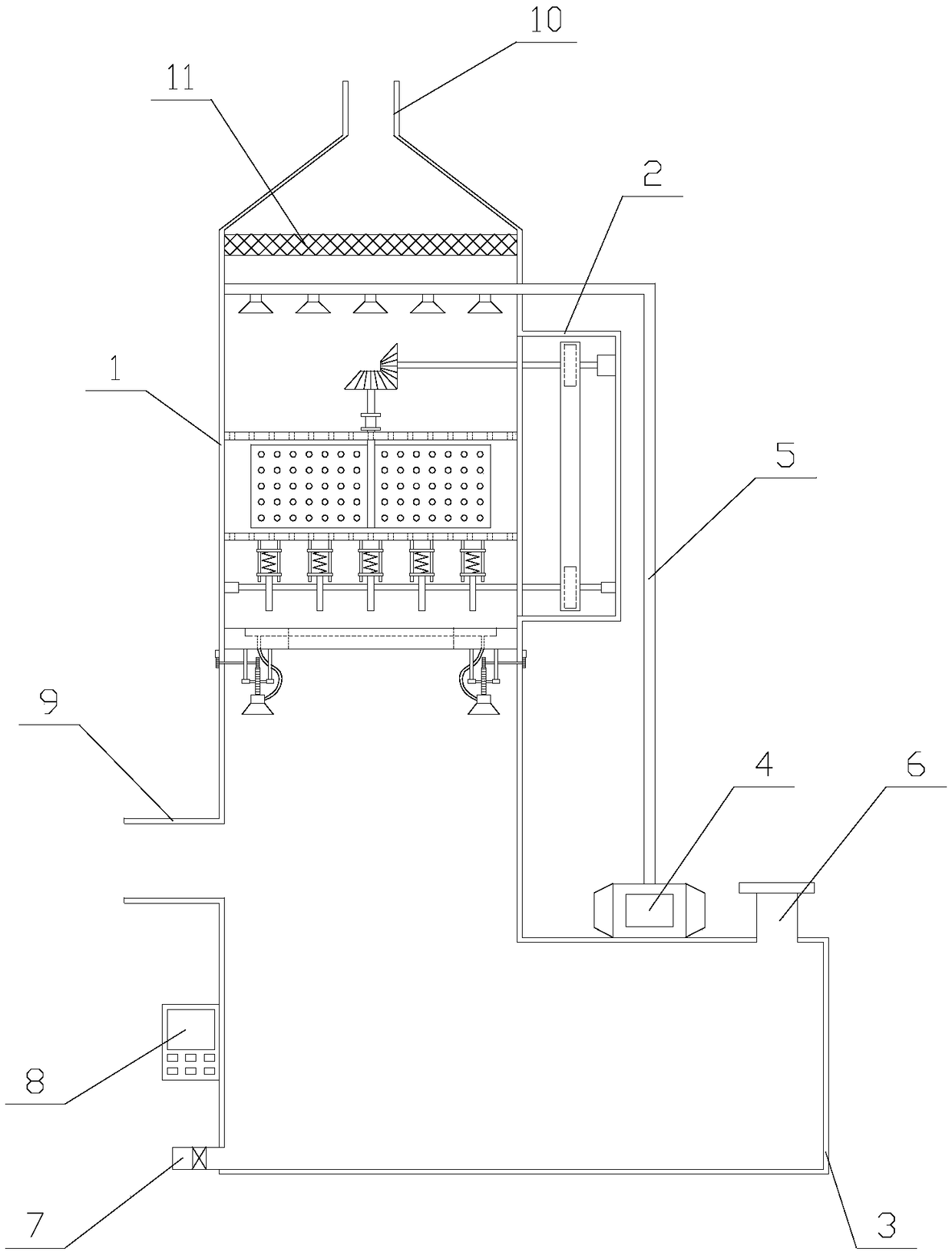
[0026] Such as figure 1 As shown, a spray tower for preventing wall flow includes a tower body 1, a driving chamber 2, a water tank 3, a water pump 4, a suction pipe 5, a water injection pipe 6, a drain pipe 7, a controller 8, an air intake pipe 9 and an exhaust pipe 10. The air inlet pipe 9 is located on one side of the tower body 1, the driving chamber 2 is fixed on the other side of the tower body 1, and the tower body 1, the water injection pipe 6 and the water pump 4 are all fixed above the water tank 3, The top of the water injection pipe 6 is provided with a cover plate, the exhaust pipe 10 is positioned at the top of the tower body 1, the controller 8...


PUM


Abstract

The invention relates to a wall-flow preventing spray tower which comprises a tower body, a driving chamber, a water tank, a water pump, a water suction pipe, an air intake pipe and an air exhaust pipe; a spray mechanism comprises a mixing component, a vibrating component and a plurality of first spray heads; the mixing component comprises a first bevel wheel, a second bevel wheel, a rotation shaft, a support unit, a first mesh plate, a second mesh plate and two mixing plates; a wall-flow preventing mechanism comprises a circular ring and a plurality of water spray components; and each water spray component comprises a first gear, a second gear, a second spray head, a connecting pipe, a concentric shaft, a power component and two connecting components. The wall-flow preventing spray towerhas the advantages that the spray mechanism drives the mixing plate to rotate, and a vibrating plate is enabled to knock the lower side of the second mesh plate, therefore, a filler between the firstmesh plate and the second mesh plate is enabled to be evenly distributed for being convenient in full absorption of acidic materials in exhaust gas; furthermore, an alkali liquid flowing downward is evenly sprayed onto the lower part inside the tower body through the wall-flow preventing mechanism and is convenient to be in sufficient contact with the exhaust gas for reacting, thereby improving the practicability of equipment.

Description

technical field [0001] The invention relates to the field of air purification equipment, in particular to a spray tower for preventing wall flow. Background technique [0002] The spray tower is a kind of equipment for waste gas treatment, and such purification equipment is often used in industrial waste gas treatment. Its working principle is: the acid mist exhaust gas is introduced into the purification tower through the air duct, and after passing through the packing layer, the exhaust gas and the sodium hydroxide absorption liquid undergo full gas-liquid two-phase contact absorption and neutralization reaction. After the acid mist exhaust gas is purified, it is then demisted. After the plate is dehydrated and defogged, it is discharged into the atmosphere by the fan to achieve purification. [0003] When the spray tower is in operation, the gas is fed from the bottom of the tower, and after being distributed by the gas distribution device, it flows countercurrently with...

Claims


Application Information

Patent Timeline
Patent Type & Authority Applications(China)
IPC IPC(8): B01D53/78B01D53/40
CPCB01D53/40B01D53/78B01D2258/06
Inventor 陈科
Owner SHENZHEN LEILING GUANGTONG TECH DEV CO LTD
Why Eureka
Try Eureka