Collimator position and posture adjustment device and method for laser assisted milling

A laser-assisted and adjusting device technology, applied in the details of milling machine equipment, milling machine equipment, metal processing equipment, etc., can solve problems such as affecting processing efficiency, affecting cutting effect, tool wear, etc., to reduce vibration and laser spot offset, Guaranteed accuracy and processing stability, compact overall structure and layout

Active Publication Date: 2018-11-20
HUAZHONG UNIV OF SCI & TECH
View PDF10 Cites 7 Cited by
  • Summary
  • Abstract
  • Description
  • Claims
  • Application Information

AI Technical Summary

Problems solved by technology

In the process of laser-assisted milling, the temperature of laser preheating directly affects the cutting effect. If the laser spot is too small, the heat absorbed by the workpiece will be concentrated in a small area, and the temperature gradient will be large, which will easily cause thermal stress and microscopic cracks; if the laser spot If the value is too large, the heat absorbed by the workpiece will be dispersed in a larger area, and the temperature gradient will be small. Although the effect on thermal stress is small, it will directly affect the processing efficiency
The distance between the light spot and the tool will also affect the cutting effect. If the distance is too large, the preheating effect of the cutting area will not be ideal. If the distance is too small, it will easily cause thermal shock / fatigue of the tool and aggravate tool wear.

Method used


Image

  • Collimator position and posture adjustment device and method for laser assisted milling
  • Collimator position and posture adjustment device and method for laser assisted milling
  • Collimator position and posture adjustment device and method for laser assisted milling

Examples


Embodiment Construction

[0034] In order to make the object, technical solution and advantages of the present invention clearer, the present invention will be further described in detail below in conjunction with the accompanying drawings and embodiments. It should be understood that the specific embodiments described here are only used to explain the present invention, not to limit the present invention. In addition, the technical features involved in the various embodiments of the present invention described below can be combined with each other as long as they do not constitute a conflict with each other.

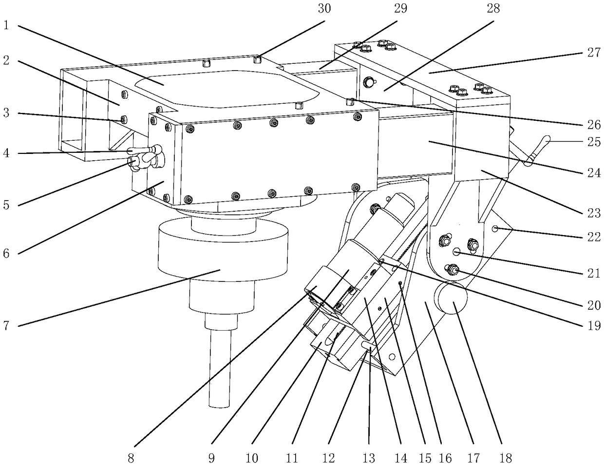
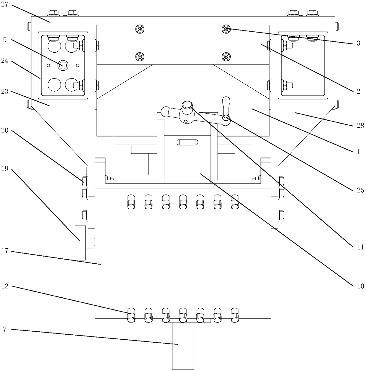
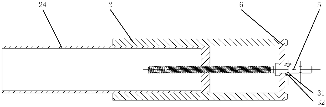
[0035] Such as figure 1 As shown, the embodiment of the present invention provides a collimator posture adjustment device for laser-assisted milling, which includes a fixed support plate 2, a pair of parallel square slide rails 24, 29, a U-shaped movable support back 17 and cross slide mechanism, wherein, a pair of parallel square slide rails 24,29 are installed on both sides of the fixed supp...


PUM


Abstract

The invention belongs to the field of collimator position and posture adjustment, and particularly discloses a collimator position and posture adjustment device and method for laser assisted milling.The collimator position and posture adjustment device comprises a fixed supporting plate, a pair of parallel square slide rails, a U-shaped movable supporting back and a cross slide platform mechanism, wherein the pair of parallel square slide rails is installed on both sides of the fixed supporting plate, and two fixed supporting backs are correspondingly mounted at the ends, away from the fixedsupporting plate, of the two square slide rails; and the two fixed supporting backs are connected with the U-shaped movable supporting back in pivoted and rotating modes so as to form a rotary pair, the cross slide platform mechanism is mounted on the U-shaped movable supporting back, and a collimator is mounted on the cross slide platform mechanism. The method is performed by using the collimatorposition and posture adjustment device to achieve the adjustment of the laser incident angle, spot size, and the relative position between a laser spot and a tool. The collimator position and postureadjustment device can effectively adjust the position and posture of the collimator, has a compact overall structural layout, small size and small space occupation.

Description

technical field [0001] The invention belongs to the field of collimator posture adjustment, and more particularly relates to a collimator posture adjustment device and method used in laser-assisted milling. Background technique [0002] With the development of the national aerospace industry, aircraft carrier industry and other industries, there are stricter requirements on the performance of product parts and materials, and various high-hardness and high-strength engineering materials (such as AerMet100 steel, titanium alloys) have emerged. When the traditional milling process is used to process difficult-to-machine materials such as AerMet100 steel and titanium alloy, the tool is prone to problems such as sticking, chip breaking and easy wear of the tool, and the processing efficiency is low. The use of laser-assisted milling technology can effectively reduce the cutting force and inhibit the generation of built-up edge, and at the same time can improve the sticking phenom...

Claims


Application Information

Patent Timeline
Patent Type & Authority Applications(China)
IPC IPC(8): B23P25/00B23C3/00
CPCB23C3/00B23P25/006
Inventor 闫蓉彭芳瑜曾浩浩杜鹏乐汪伟胡甜甜唐小卫
Owner HUAZHONG UNIV OF SCI & TECH
Why Eureka
Try Eureka