Continuous round can discharging and conveying mechanism

A technology of conveying mechanism and round cans, which is applied to conveyors, conveyor objects, stacking of objects, etc., can solve the problems of long working time, affecting the quality of round cans, falling off of round cans, etc., and achieves structural design. reasonable effect

Inactive Publication Date: 2018-11-20
徐晓杰
View PDF0 Cites 4 Cited by
  • Summary
  • Abstract
  • Description
  • Claims
  • Application Information

AI Technical Summary

Problems solved by technology

For metal round cans, after the tinplate is produced and processed into round cans by the previous process, the upper cover of the round cans needs to be processed, and the round cans produced and processed by the previous process are smoothly carried out along the conveyor belt For transmission, the round cans need to be placed one by one to the upper cover processing station for processing. In the subsequent production and processing process of the existing round cans, for small can making enterprises, the manual processing is generally mainly used to complete the previous process. The round cans are manually placed to the required processing station to enable the upper cover processing. The workers' work intensity is high and the working hours are long, which makes it difficult to meet the needs of large-scale can production. The existing large-scale can production enterprises , in the process of placing the round tank body produced and processed in the previous process, the manipulator is generally used to automatically grab and place it, but to use the manipulator to place it, it is first necessary to grab the round tank body. The existing manipulator will In the process of grabbing the round tank, the round tank often falls off due to poor grasping in the process of grabbing the round tank, so that the round tank cannot be normally grabbed and placed, making the The efficiency and quality of circular tank placement cannot be guaranteed, and in the process of grabbing the circular tank with the manipulator, the circular tank is often flattened and twisted due to improper grasping force, which affects the round tank. The quality of the shaped cans, especially when there is a height difference between the round cans transmission mechanism and the upper cover processing station, in the process of grabbing and placing the round cans, the cans need to be raised and lowered in the vertical direction. As a result, the manipulator needs multiple driving mechanisms to drive continuously and independently, the driving energy consumption is high, and the multi-driving mechanisms are also prone to failures, making it difficult to operate stably for a long period of time, and it cannot guarantee continuous and efficient circular tanks one by one. Material placement, the existing circular cans placed in the can feeding tube are difficult to realize accurate feeding one by one, which affects the subsequent normal transmission and upper cover processing of the circular tank, and the existing can feeding tube is difficult to apply Various sizes and specifications of circular tanks are placed and unloaded. For circular tanks of different sizes and specifications, it is necessary to install matching tank feeding tubes. It is troublesome to use and the scope of application is narrow, which cannot meet the needs of production and use.

Method used


Image

  • Continuous round can discharging and conveying mechanism
  • Continuous round can discharging and conveying mechanism
  • Continuous round can discharging and conveying mechanism

Examples


Embodiment Construction

[0017] In order to further describe the present invention, a specific implementation of a round can continuous unloading conveying mechanism will be further described below in conjunction with the accompanying drawings. The following examples are explanations of the present invention and the present invention is not limited to the following examples.

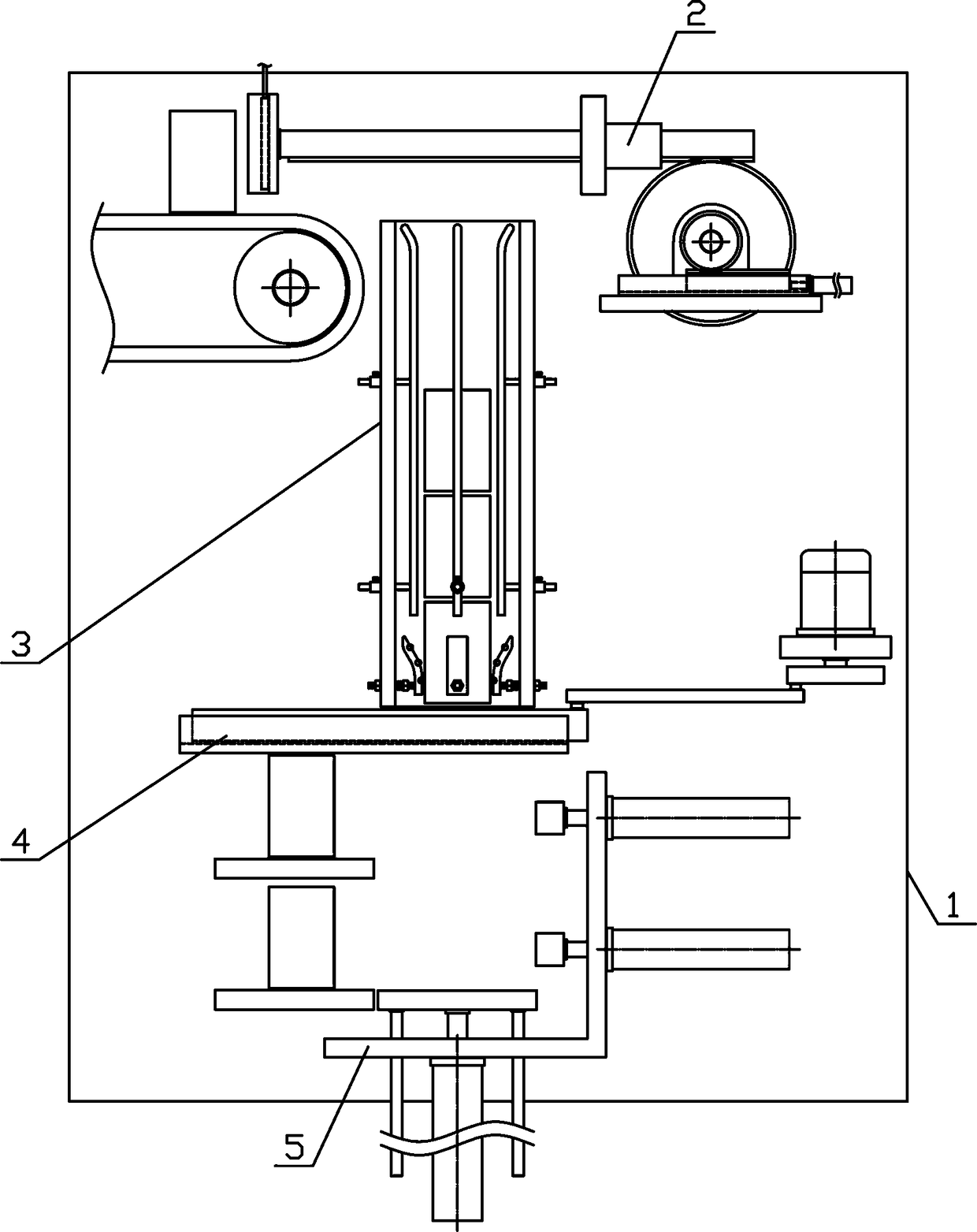
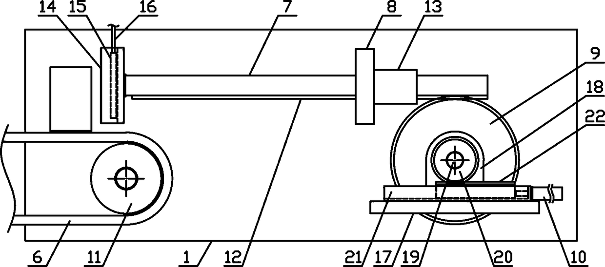
[0018] Such as figure 1 As shown, a round can continuous unloading transmission mechanism of the present invention includes a fixed bracket 1, a can moving mechanism 2, a can guiding mechanism 3, a can lowering mechanism 4 and a can pushing mechanism 5, and the can moving mechanism 2, can guiding mechanism 5 of the present invention The mechanism 3, the can lowering mechanism 4 and the can pushing mechanism 5 are sequentially arranged on one side of the fixed bracket 1 from top to bottom. Such as figure 2 As shown, the can transfer mechanism 2 of the present invention includes a can transfer belt 6, a material transfer guide r...


PUM


Abstract

The invention discloses a continuous round can discharging and transferring mechanism, and belongs to the field of vessel processing machinery and equipment. According to the continuous round can discharging and transferring mechanism, a can moving mechanism, a can guide mechanism, a can discharging mechanism and a can pushing mechanism are arranged on one side of a fixed bracket in sequence fromtop to bottom, a material moving guide rod is arranged on a guide bracket in a sliding mode in a horizontal direction, a plurality of limiting stop levers are vertically and uniformly arranged on theupper side of a can guide channel, a plurality of buffer pressing plates are vertically and uniformly arranged on the lower side of the can guide channel, a translating connecting plate is arranged ona translating bracket in the sliding mode in the horizontal direction, a discharge through hole is horizontally formed in one side of the translating connecting plate, a can supporting cylinder is vertically and fixedly arranged on the lower side of a can pushing bracket upwards, and an upper station connecting plate and a lower station connecting plate are horizontally and fixedly arranged on the fixed bracket on one side of the can pushing bracket in sequence from top to bottom. The continuous round can discharging and transferring mechanism has the advantage of reasonable structural design, round cans can be continuously and stably discharged one by one, the round cans can be precisely pushed in several directions one by one, and the production and use requirements are met.

Description

technical field [0001] The invention belongs to the field of container equipment processing machinery and equipment, and in particular relates to a continuous feeding and conveying mechanism for round cans, which is mainly used in the field of continuous production and processing of round cans. Background technique [0002] Tanks mainly refer to cylindrical airtight containers that can be used to store materials. Tanks play an increasingly important role in our production and life due to their high efficiency in storing items and the convenience of carrying them. Tanks are classified according to their appearance and shape. , can be divided into square cans and round cans. There are many materials for producing cans, mainly including plastic cans and metal cans. Compared with plastic cans, metal cans are more widely used in our industrial production and daily life. The advantages of metal cans Obviously, its airtight performance is very good, it can resist high internal pres...

Claims


Application Information

Patent Timeline
Patent Type & Authority Applications(China)
IPC IPC(8): B65G47/90B65G57/03
CPCB65G47/902B65G57/03B65G2201/0252
Inventor 徐晓杰
Owner 徐晓杰
Why Eureka
Try Eureka