A vehicle stability test device
An experimental device and stability technology, applied in the direction of measuring device, vehicle test, machine/structural component test, etc., can solve problems such as loss of experimental device and experimental equipment, large critical speed of vehicle instability, and real vehicle instability
- Summary
- Abstract
- Description
- Claims
- Application Information
AI Technical Summary
Problems solved by technology
Method used
Image
Examples
Embodiment 1
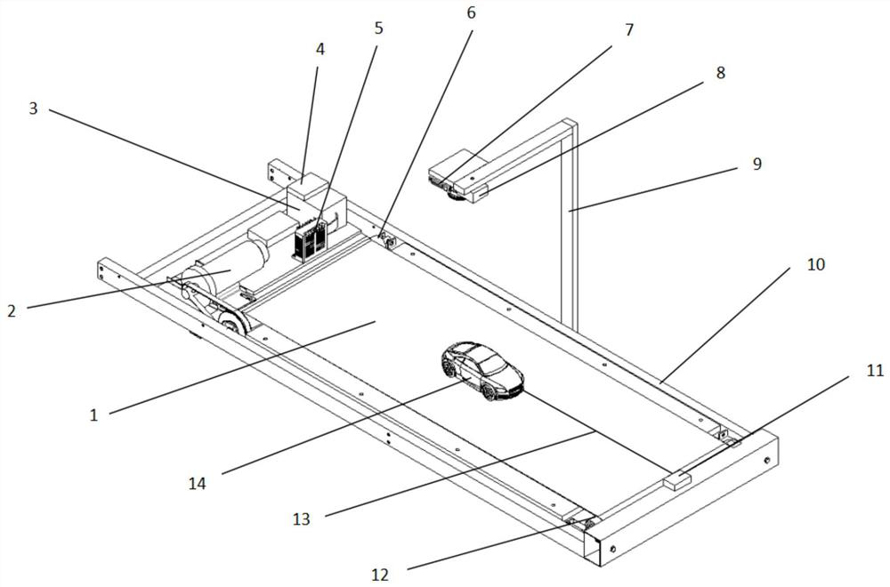
[0038] see figure 1 , vehicle stability test device includes: belt 1, DC motor 2, PLC module 3 (for example: Mitsubishi PLC module), speed display module 4, motor controller 5, front roller 6, camera 7, grid laser 8, laser bracket 9. Support platform 10, tension sensor and signal amplifier 11, rear end roller 12, traction rope 13 and vehicle model 14. Among them, the above-mentioned devices 1-13 are combined to form an experimental platform.
[0039] Wherein, the DC motor 2 is fixed on the supporting platform 10, and a roller (i.e., a front-end roller 6 and a rear-end roller 12) is respectively installed at the front and rear ends of the support platform 10, and the belt 1 is set on the rollers at the front and rear ends, and the front-end roller 6 passes through the conveyor belt It is connected to the DC motor 2, the DC motor 2 is connected to the motor controller 5 through wires, and the PLC module 3 is connected to the speed display module 4 and the motor controller 5 thr...
Embodiment 2
[0044] The solution in Embodiment 1 is further introduced in the car scene below, see the description below for details:
[0045] see figure 1 , turn on the power supply of the experimental platform, the Mitsubishi PLC module 3 runs the PLC program, outputs the voltage signal to the motor controller 5 through A / D conversion, and displays the speed value on the speed display module 4 at the same time, at this time the DC motor 2 of the experimental platform starts, Belt 1 starts running.
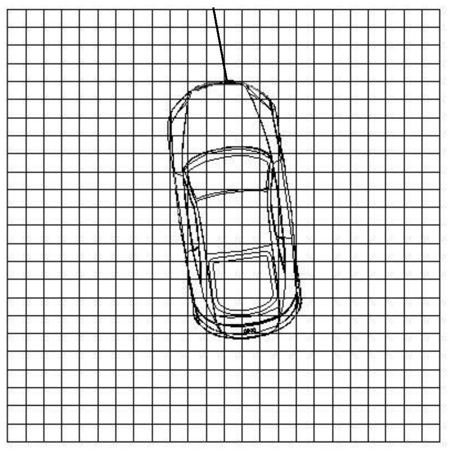
[0046] During the working process, the grid laser 8 will project grid lines of a certain area to the experimental platform (consisting of devices 1-13), such as figure 2 As shown, the specific size and total projected area of each grid are measured and marked on the vehicle model, the camera shoots the experimental platform, and the real-time lateral displacement and attitude of the vehicle model can be obtained by using image processing technology. At the same time, the tension sensor a...
Embodiment 3
[0050] The scheme in embodiment 1 is further introduced in the train scene below, see the following description for details:
[0051] see figure 1 , turn on the power supply of the experimental platform, the Mitsubishi PLC module 3 runs the PLC program, outputs the voltage signal to the motor controller 5 through A / D conversion, and displays the speed value on the speed display module 4 at the same time, at this time the DC motor 2 of the experimental platform starts, Belt 1 starts running.
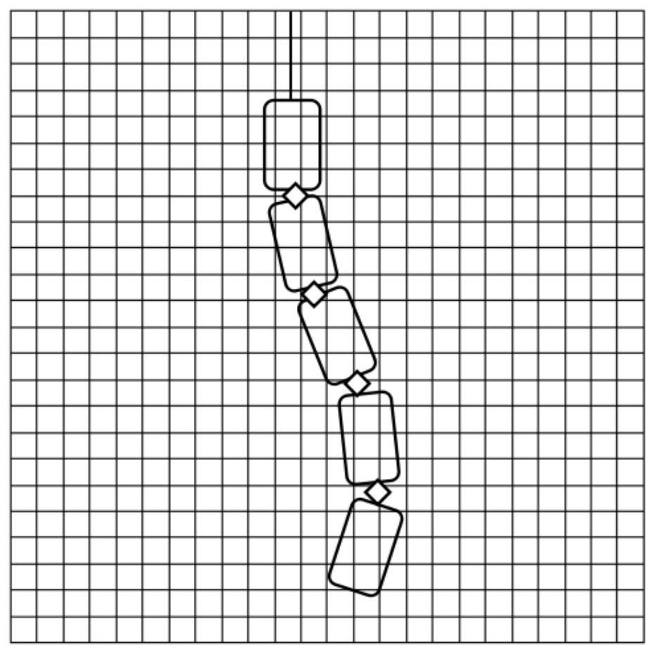
[0052] During the working process, the grid laser 8 will project grid lines of a certain area to the experimental platform (consisting of devices 1-13), such as image 3 As shown, the specific size and total projected area of each grid are measured, and marked on each carriage of the train model, the camera shoots the experimental platform, and the real-time lateral view of the train model can be obtained by using image processing technology. displacement and posture. At the same tim...
PUM
 Abstract
Description
Claims
Application Information
 - R&D
- Intellectual Property
- Life Sciences
- Materials
- Tech Scout
- Unparalleled Data Quality
- Higher Quality Content
- 60% Fewer Hallucinations
Browse by: Latest US Patents, China's latest patents, Technical Efficacy Thesaurus, Application Domain, Technology Topic, Popular Technical Reports.
© 2025 PatSnap. All rights reserved.Legal|Privacy policy|Modern Slavery Act Transparency Statement|Sitemap|About US| Contact US: help@patsnap.com


