

Industrial remote controller
A remote control and industrial technology, applied in the field of automatic control, can solve the problems of troublesome operation, inconvenient operation, and high after-sales cost for users, and achieve the effect of reducing matching costs, improving anti-interference ability, and simple after-sales service
- Summary
- Abstract
- Description
- Claims
- Application Information
AI Technical Summary
Problems solved by technology
Method used
Image

Examples
Embodiment 1
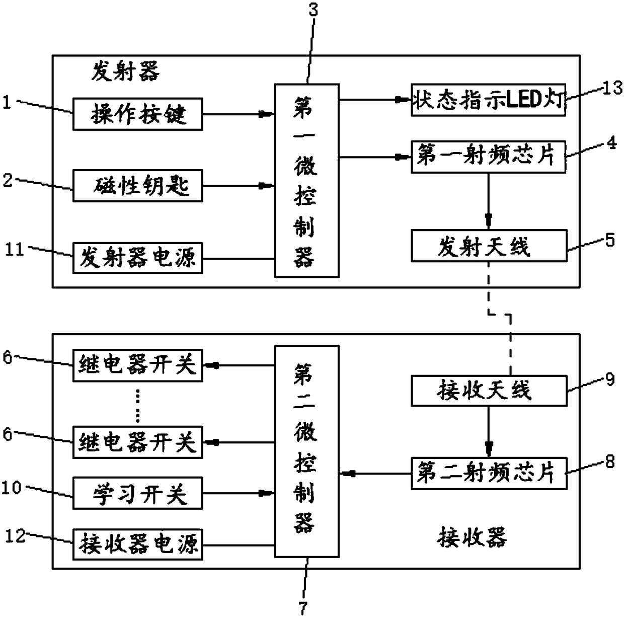
[0039] The invention provides an industrial remote control, specifically as figure 1 As shown, including the transmitter and receiver, both the receiver and the transmitter have a learning function. The transmitter includes an operation button 1, a magnetic key 2, a first microcontroller 3, a first radio frequency chip 4, and a transmitting antenna 5, and the receiver includes a second microcontroller 7, a second radio frequency chip 8, a receiving antenna 9, and a learning switch 10 and multi-way relay switch 6;
[0040] The connection relationship of each part is: the operation button 1 and the magnetic key 2 are all electrically connected to the signal input end of the first microcontroller 3, and the signal receiving end of the first radio frequency chip 4 is electrically connected to the signal output end of the first microcontroller 3. Connect, the signal transmitting end of the first radio frequency chip 4 is electrically connected with the transmitting antenna 5;
[...
PUM
 Abstract
Description
Claims
Application Information