
Multi-band MIMO terminal antenna based on ground radiation mode

A radiation mode and terminal antenna technology, which is applied to the structural form of the radiation element, antenna, antenna grounding device, etc., to achieve the effect of reducing physical size, improving space utilization, and increasing the electrical length of the antenna

Active Publication Date: 2018-11-20
HANGZHOU DIANZI UNIV
View PDF10 Cites 10 Cited by
  • Summary
  • Abstract
  • Description
  • Claims
  • Application Information

AI Technical Summary

Problems solved by technology

Therefore, making the best choice between the size of the antenna and its radiation performance is the main challenge

Method used


Image

  • Multi-band MIMO terminal antenna based on ground radiation mode
  • Multi-band MIMO terminal antenna based on ground radiation mode
  • Multi-band MIMO terminal antenna based on ground radiation mode

Examples


Embodiment 1

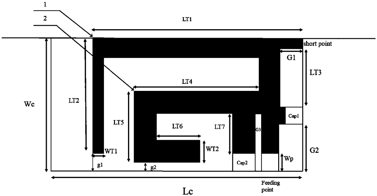
[0024] Such as figure 1 As shown, in the rectangular clearance area at the edge of the metal ground of the antenna unit of the present invention, the antenna unit has two open annular metal strips, which are nested and connected together, and the structure of multiple metal strips nested is used to realize the multiple functions of the ground radiation antenna. frequency band resonance. At the same time, a desired resonant frequency can be achieved with a smaller physical size by loading a capacitor, and the capacitor is loaded between the metal strip and the metal ground. The feeding method adopts coaxial feeding.

[0025] It should be noted that the first radiating metal strip 1 of the outer layer cannot fully envelop the second radiating metal strip 2 of the inner layer (ie figure 1 where g1 is greater than g2), otherwise the radiation performance of the second radiation metal strip 2 will be affected.

Embodiment 2

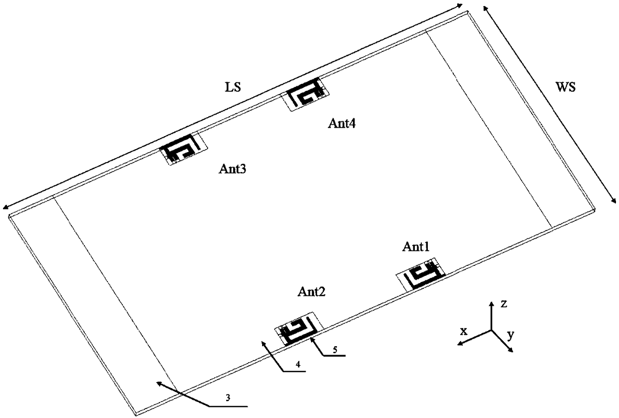
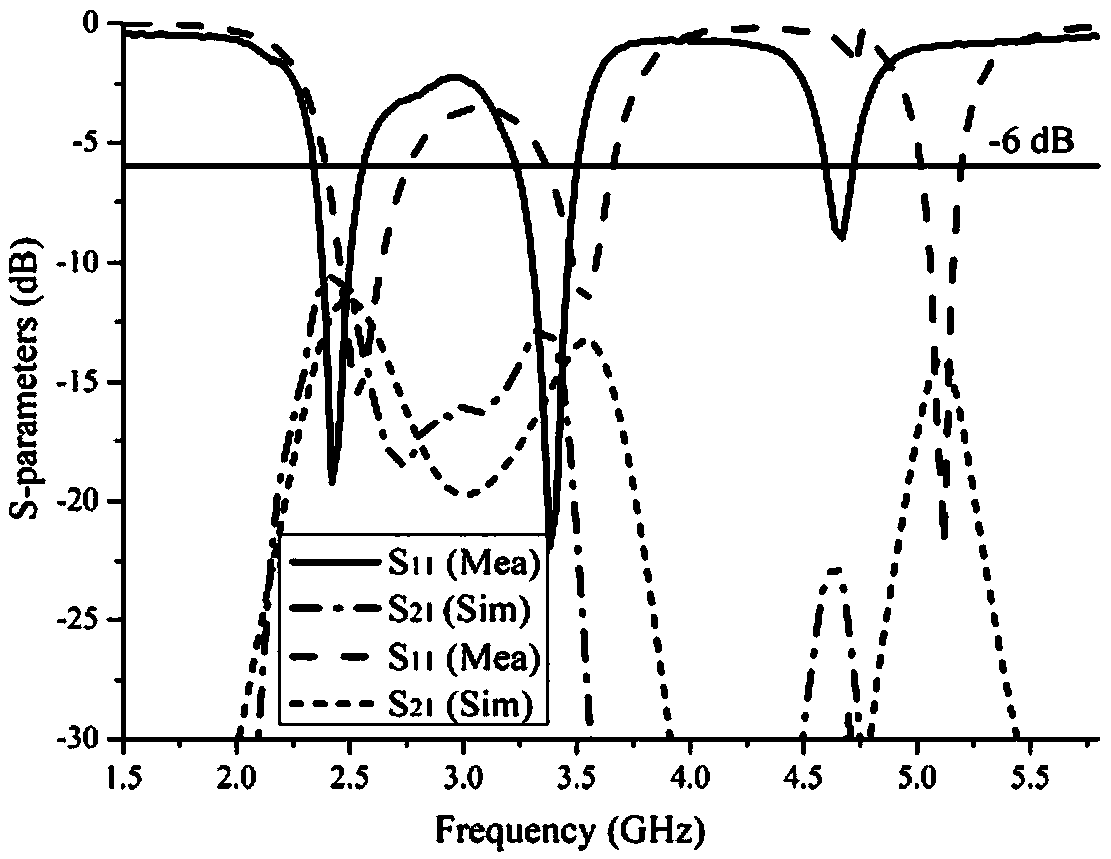
[0027] Such as figure 2 As shown, the MIMO antenna system of the present invention includes a dielectric substrate 3, a metal ground 4, and an antenna unit 5; two of the four antenna units are placed on one side edge of the dielectric substrate, and the other two are placed on the opposite side edge of the dielectric substrate , others as metal ground. The antenna elements can be placed in a mirrored structure and can be fed by a coaxial feeder. It should be noted that there is no decoupling structure between the antenna elements. figure 1 In , the spacing between adjacent antennas has been optimized to meet the requirement of isolation below -10dB.

[0028] The design of the antenna in this example is carried out in the 3D electromagnetic simulation software HFSS, and the relevant dimensions are determined by software optimization, as shown in the following table:

[0029] Parameters

LS

WS

Lc

wc

LT1

LT2

Unit(mm)

130

70

11....


PUM


Abstract

The invention discloses a multi-band MIMO terminal antenna based on a ground radiation mode. The antenna comprises a dielectric substrate, a metal ground and a plurality of antenna units; the plurality of antenna units are arranged on the edge of the dielectric substrate, and the metal ground is paved on other positions; the adjacent antenna units are arranged in a mirror symmetry mode, and the antennas is fed by a coaxial feeder line; each antenna unit comprises a first radiation metal strip and a second radiation metal strip, wherein the first radiation metal strip and the second radiation metal strip extend from a feed opening; the second radiation metal strip is embedded in the first radiation metal strip; and the radiation branch root parts of the first and the second radiation metalstrips are connected with the metal ground through capacitors C1 and C2. By virtue of the nesting structure of the metal strips, the multi-band mode of the ground antenna is achieved, and the space utilization rate of the antenna is improved; and meanwhile, the capacitors are connected in parallel between the multi-layer nesting structure and the metal ground, so that the electric length of the antenna is prolonged, and the physical size of the antenna is reduced.

Description

technical field [0001] The invention belongs to the technical field of wireless communication, and proposes a multi-band MIMO terminal antenna based on a ground radiation mode and applied to WLAN frequency bands and future 5G communication frequency bands. Background technique [0002] With the development of wireless communication technology, wireless communication has higher and higher requirements for antennas. The radiation performance of most antennas is closely related to the size. The larger the size, the better the overall performance. However, more and more functions are integrated into the terminal equipment nowadays, and the space of the equipment is becoming more and more compact, resulting in a smaller and smaller size of the antenna. Since the impedance bandwidth of the antenna is closely related to the physical size. Therefore, making the best choice between the size of the antenna and its radiation performance is the main challenge. [0003] Ground Radiat...

Claims


Application Information

Patent Timeline
Patent Type & Authority Applications(China)
IPC IPC(8): H01Q1/38H01Q1/48H01Q1/50H01Q5/314
CPCH01Q1/38H01Q1/48H01Q1/50H01Q5/314
Inventor 徐魁文段江波徐正陈世昌赵文生赵鹏王高峰
Owner HANGZHOU DIANZI UNIV
Learn More