Sleeve pipe section cutting and denting device

A casing and extrusion molding technology, applied in other manufacturing equipment/tools, metal processing, manufacturing tools, etc., can solve problems such as difficult product quality assurance, dragging down processing progress, low work efficiency, etc., to ensure processing progress, The effect of reducing labor intensity and improving processing efficiency

Pending Publication Date: 2018-11-23
ANHUI PALLET INTELLIGENT EQUIP CO LTD
View PDF0 Cites 0 Cited by
  • Summary
  • Abstract
  • Description
  • Claims
  • Application Information

AI Technical Summary

Problems solved by technology

[0002] The casing is used as a protective shell on the outside of the workpiece. In order to meet the requirements of different products, the casing will be cut and concaved into sections according to the needs. However, when cutting the casing in the traditional production line, most of the materials are manually fed. The labor intensity is high, the work efficiency is low, and it is easy to delay the processing progress due to mistakes. At the same time, when the casing is cut, due to the softness and variability of the casing, the location of the casing is difficult to fix, the cutting stability is poor, and the product quality is difficult to guarantee. Not conducive to the processing of casing

Method used


Image

  • Sleeve pipe section cutting and denting device
  • Sleeve pipe section cutting and denting device
  • Sleeve pipe section cutting and denting device

Examples


Embodiment Construction

[0018] In order to make the technical means, creative features, goals and effects achieved by the present invention easy to understand, the present invention will be further elaborated below.

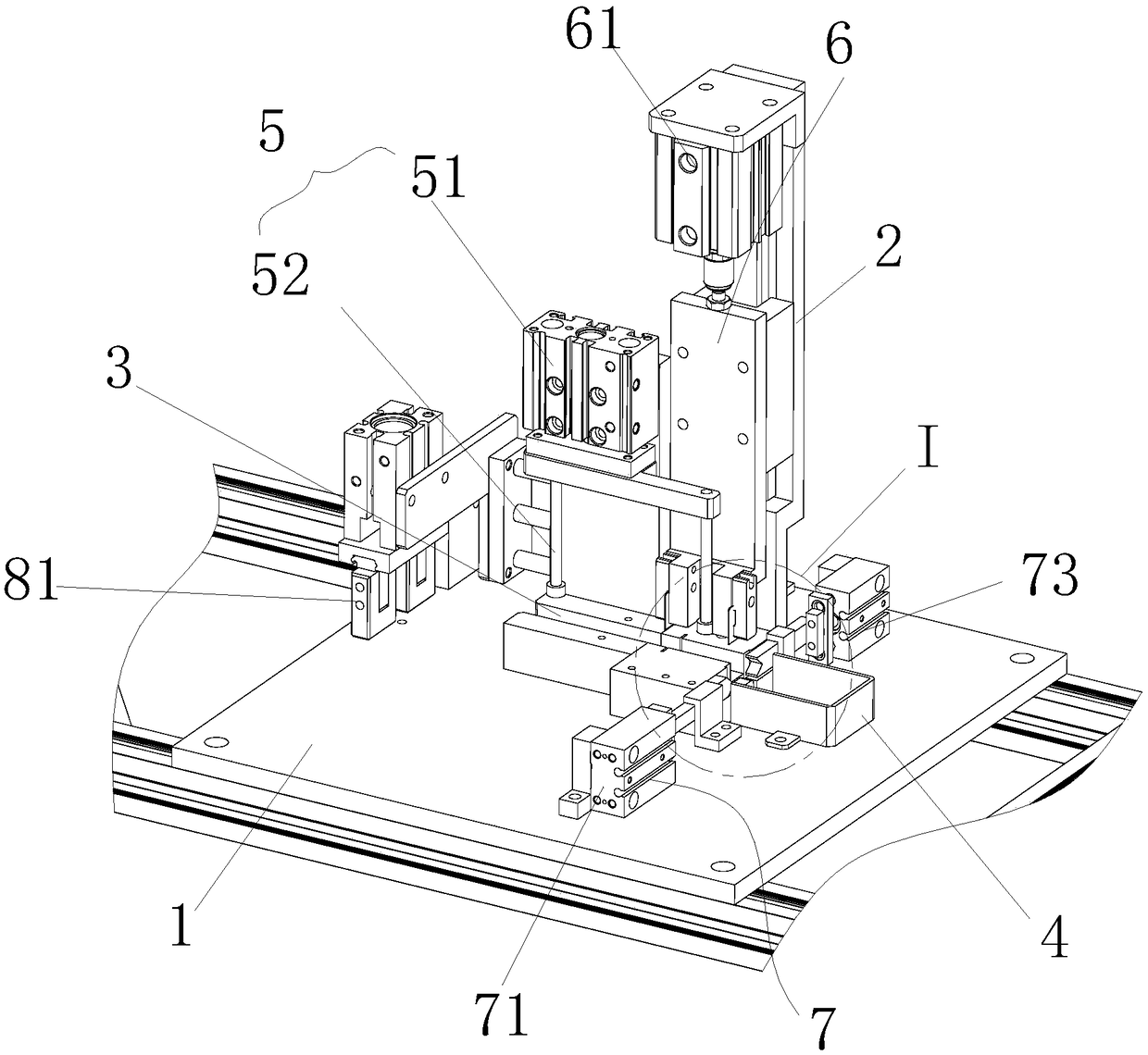
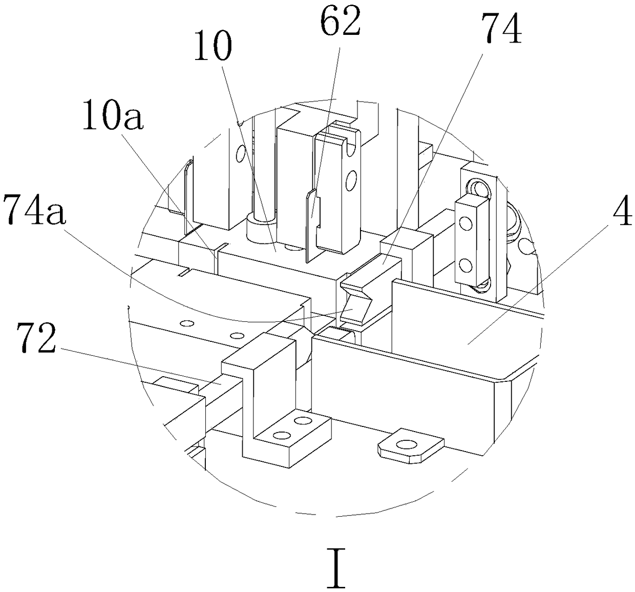
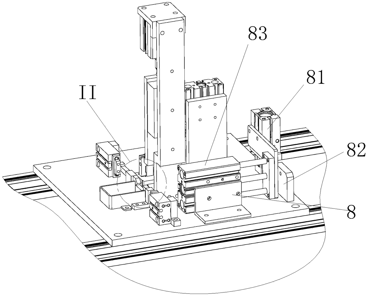
[0019] Such as Figure 1 to Figure 5 As shown, a casing segment cutting and pressing concave device includes a bottom plate 1, on which a support 2, a guide groove block 3 for the casing 9 to pass, and a U-shaped The baffle plate 4, the pressing mechanism 5 fixed on the support 2 and moving down against the casing 9, the cutting mechanism 6 cutting off the casing 9, two extrusion molding mechanisms 7 located on both sides of the axis of the casing 9, The conveying mechanism 8 that is arranged near the feeding end of the guide groove block 3 .

[0020] The pressing mechanism 5 includes a push-down cylinder 51 and two compression round rods 52 connected with the output end of the push-down cylinder 51 and extending into the guide groove block 3 . In this manner, it is ensured that the s...


PUM


Abstract

The invention relates to a sleeve pipe section cutting and denting device. The sleeve pipe section cutting and denting device comprises a bottom plate; a supporting base, a guiding grooved block, a U-shaped baffle plate, a compressing mechanism, a cutting mechanism, two extrusion moulding mechanisms and a conveying mechanism are arranged on the bottom plate; the guiding grooved block is used for asleeve pipe to penetrate through; the U-shaped baffle plate is located at the free end part of the sleeve pipe; the compressing mechanism is fixed on the supporting base and moves downwards to abut against the sleeve pipe; the cutting mechanism is used for cutting off the sleeve pipe; the two extrusion moulding mechanisms are located on two sides of the axis of the sleeve pipe; and the conveyingmechanism is close to the material inlet end of the guiding grooved block. By adopting the sleeve pipe section cutting and denting device, manpower can be replaced for achieving stable conveying for the sleeve pipe; labor intensity is alleviated; manual error is avoided; the machining process is ensured; further, the sleeve pipe can be accurately positioned and clamped; cutting stability is higher; product quality is better; the whole device is simple to operate and convenient to use; automatic operation is favorably realized; and machining efficiency of sleeve pipes is improved.

Description

technical field [0001] The invention relates to the technical field of casing pipe processing, in particular to a casing section cutting and embossing device. Background technique [0002] The casing is used as a protective shell on the outside of the workpiece. In order to meet the requirements of different products, the casing will be cut and concaved into sections according to the needs. However, when cutting the casing in the traditional production line, most of the materials are manually fed. The labor intensity is high, the work efficiency is low, and it is easy to delay the processing progress due to mistakes. At the same time, when the casing is cut, due to the softness and variability of the casing, the location of the casing is difficult to fix, the cutting stability is poor, and the product quality is difficult to guarantee. It is not conducive to the processing of casing. Contents of the invention [0003] In order to avoid and solve the above-mentioned techni...

Claims


Application Information

Patent Timeline
Patent Type & Authority Applications(China)
IPC IPC(8): B23P23/04B23Q7/14
CPCB23P23/04B23Q7/14
Inventor 谭源杨修平苟巧露
Owner ANHUI PALLET INTELLIGENT EQUIP CO LTD
Why Eureka
Try Eureka