Parting lathe tool

A technology of cutting tools and cutting blades, which is applied in the direction of tool holders, cutting blades, manufacturing tools, etc., and can solve the problems of cutting cutting tools flat, coolant restrictions, etc.

Active Publication Date: 2018-11-23
KENNAMETAL INC
View PDF6 Cites 0 Cited by
  • Summary
  • Abstract
  • Description
  • Claims
  • Application Information

AI Technical Summary

Problems solved by technology

[0006] However, there is a problem with parting-off cutting tools compared to other cutting tools, which are particularly bulky

Method used


Image

  • Parting lathe tool
  • Parting lathe tool
  • Parting lathe tool

Examples


Embodiment Construction

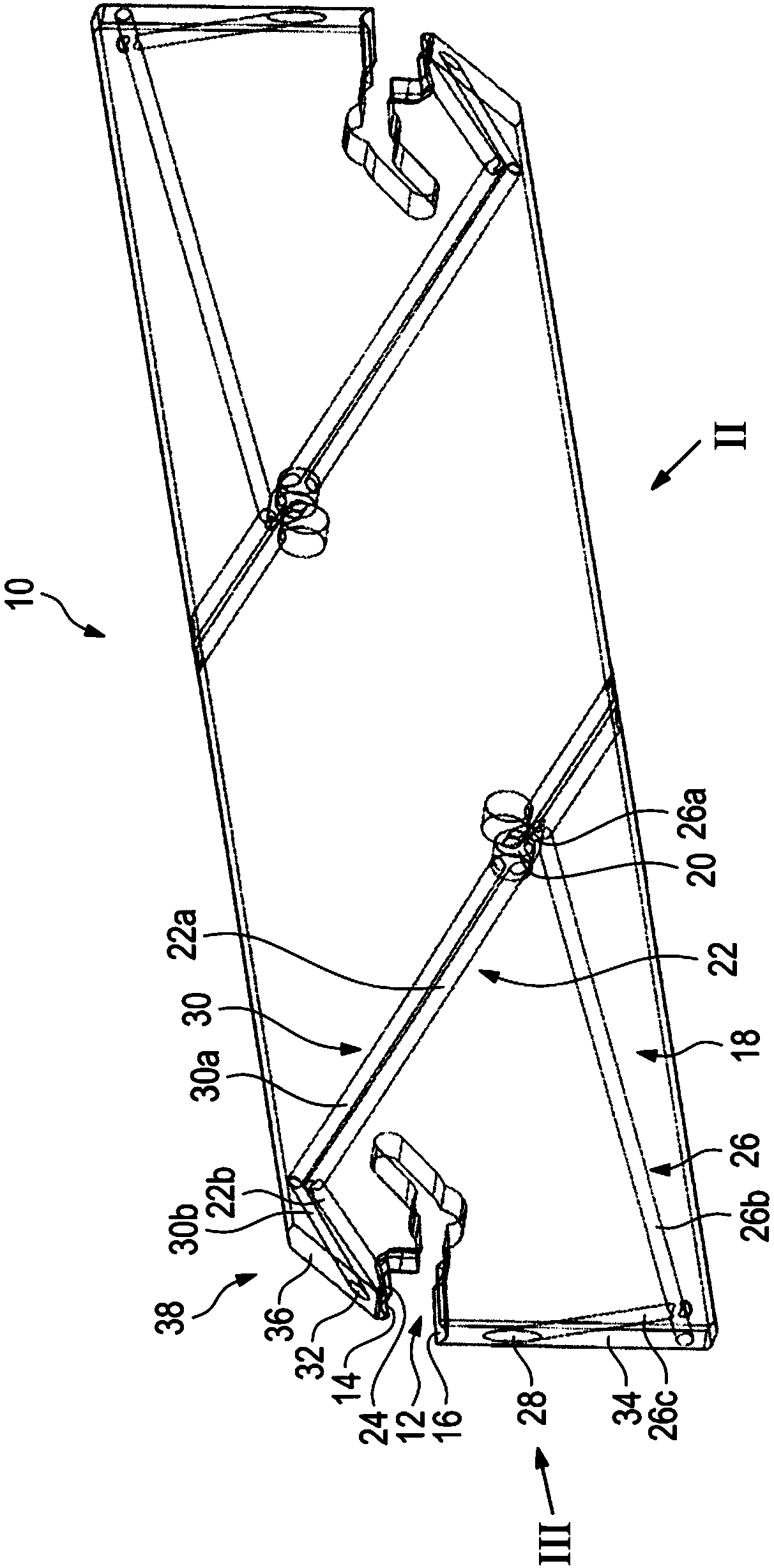
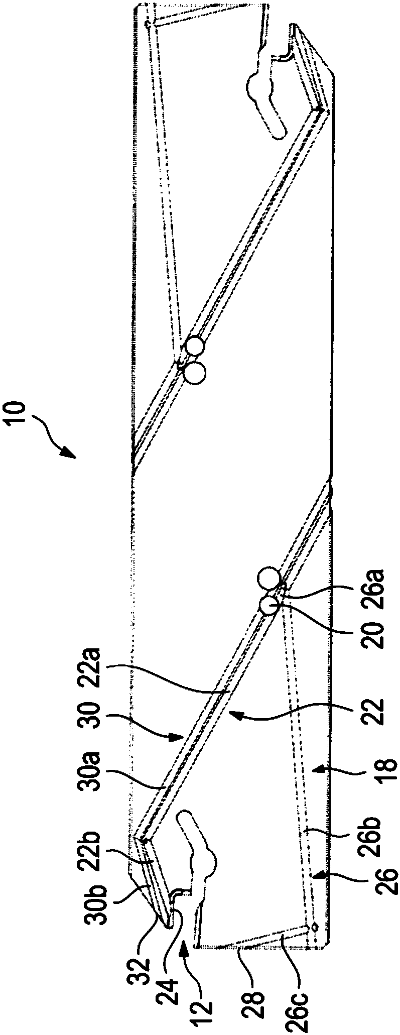
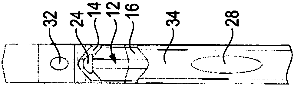
[0036] Figures 1 to 3 A parting off cutting tool 10 for cutting metal machining is shown.

[0037] The parting off cutting tool 10 may also be referred to as a parting off sword.

[0038] To accommodate cutting inserts, which are not shown in detail, which may in particular be indexable inserts, the parting-off cutting tool 10 comprises a clamping seat 12 . The clamping seat is essentially formed by two clamping surfaces 14 , 16 between which the cutting insert can be clamped.

[0039] The parting off cutting tool 10 also includes an internal coolant supply system 18 for supplying coolant to the cutting zone.

[0040] A coolant supply opening 20 is provided for this purpose on the parting-off cutting tool 10 on the part of the tool holder or on the part of the lathe.

[0041] The coolant supply opening is embodied as a substantially circular perforation and can be fluidically connected to a coolant supply outside the cut-off cutting tool 10 .

[0042] The parting off cutt...


PUM


Abstract

A parting lathe tool (10) for machining metal is described. The parting lathe tool has a clamping seat (12) for receiving a cutting insert and an internal coolant supply system (18) for supplying coolant to a cutting zone. In this case, the coolant supply system comprises at least three coolant outlets (24, 28, 32). The coolant outlets (24, 28, 32) are fluidically connected to a coolant supply port (20) via at least two separate coolant lines (22, 26, 30) running within the parting lathe tool (10).

Description

technical field [0001] The invention relates to a parting-off cutting tool for metal cutting with a holder for receiving a cutting insert and with an internal coolant supply system for supplying coolant to the cutting zone, the coolant supply system comprising At least one coolant line extends in the parting off cutting tool. Background technique [0002] Such parting-off cutting tools are known from the prior art. Such parting cutting tools are used for parting off turned parts clamped on lathes. Parting off cutting tools can also be used to make grooves. For this purpose, there are tools in different widths, which generally correspond to the groove widths to be produced. [0003] As with other cutting tools for cutting metal, in parting off cutting tools it is sought to equip the parting off cutting tool with good cutting properties, so that a high stock removal rate and thus a fast implementation of the manufacturing task can be ensured. At the same time, a high servi...

Claims


Application Information

Patent Timeline
IPC IPC(8): B23Q11/10
CPCB23Q11/10B23B27/086B23B27/10B23B29/043B23B27/04B23B27/083B23B2200/3627B23B2250/12B23B2260/0785
Inventor F.比克曼I.考夫曼
Owner KENNAMETAL INC
Why Eureka
Try Eureka