
A Parallel Compliant Wheel-Foot Device for Wheel-footed Robots

A robot and parallel technology, applied in manipulators, program-controlled manipulators, manufacturing tools, etc., can solve the problems of affecting control accuracy and stability, insufficient bearing capacity, low stiffness of foot joints, etc. Control effect, strong bearing capacity

Active Publication Date: 2021-04-02
BEIJING INSTITUTE OF TECHNOLOGYGY
View PDF10 Cites 0 Cited by
  • Summary
  • Abstract
  • Description
  • Claims
  • Application Information

AI Technical Summary

Problems solved by technology

[0005] Most of the above-mentioned wheel-foot composite mobile robots are equipped with wheels at the foot end, and the series joint mechanism is used to drive the foot end movement, and the wheel hub motor is used to drive the foot end wheel movement, resulting in insufficient load capacity and foot end dynamic characteristics of the single leg.
Its shortcomings are specifically manifested in the following four aspects: the above-mentioned wheel legs based on the tandem mechanical structure, the foot joint stiffness is small, and it is difficult to withstand high load tasks; the tandem joints cause the accumulation of position control errors, which affects the control accuracy and stability; To improve the load capacity of a single leg, hydraulic drive is required. There is a problem of noise from the hydraulic power source. In order to reduce noise, electric drive is used, which will make the load capacity insufficient; in order to improve the driving capacity of the robot’s wheeled motion, it is necessary to increase the power of the hub motor , the quality and volume of the high-power hub motor are relatively large, which makes the mass of the foot end of the robot larger, and the dynamic characteristics of the foot movement of the robot are poor

Method used


Image

  • A Parallel Compliant Wheel-Foot Device for Wheel-footed Robots
  • A Parallel Compliant Wheel-Foot Device for Wheel-footed Robots
  • A Parallel Compliant Wheel-Foot Device for Wheel-footed Robots

Examples


Embodiment Construction

[0032]The present invention will be further described in further detail below with reference to the accompanying drawings.

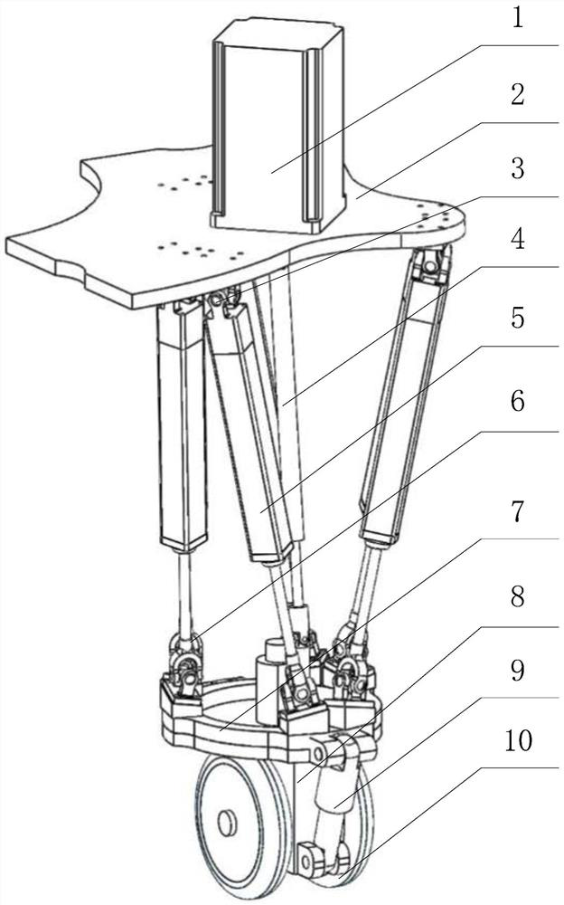
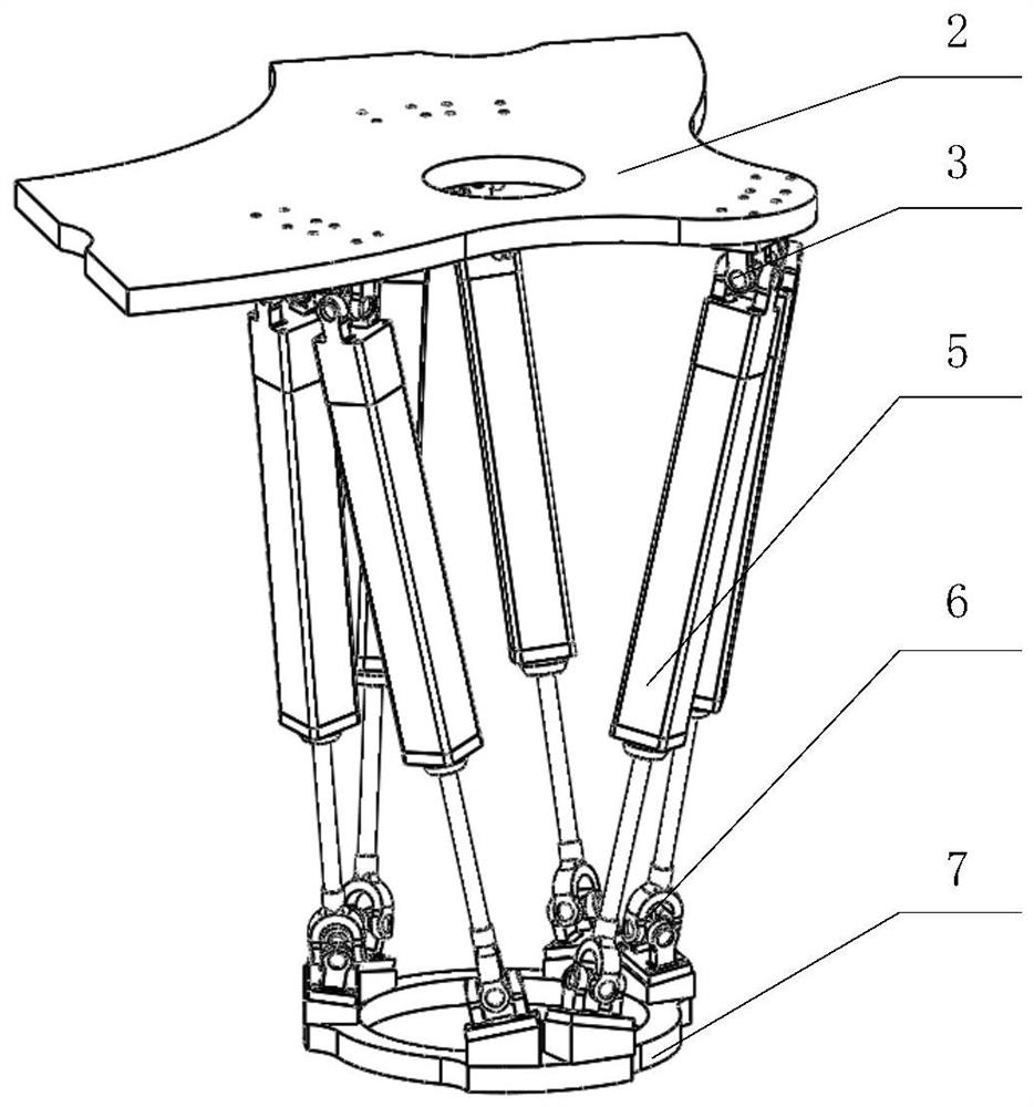
[0033]A parallel comparative pulley device for a wheelfall robot, which consists of an inverted parallel six degree of freedom motion structure and a foot-driven wheel assembly. The six-degree-of-freedom motion structure is bracketing around the foot-driven wheel assembly to make full use of space, narrowing the volume of the entire round foot device, suitable for small volume applications. Moreover, through a single free-degree spring-damping suspension design, it can be added to the foot mechanism to adjust the adjustable stiffness and damping, achieving the adaptability of the foot to the external force, is a foot-stuffed touch, and the wheel drive wheel is suspended. Important foundation.

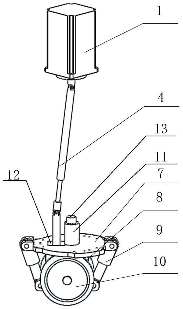
[0034]Such asimage 3 As shown, the foot-driven wheel assembly includes a drive motor 1, a transmission link 4, a reduction machine 8, a spring damper 9, and a tire 10. The dr...


PUM


Abstract

The invention discloses a parallel compliant wheel foot device for a wheeled robot. The device comprises an inverted parallel six-degree-of-freedom movement structure and a foot-end drive wheel assembly; each electric cylinder of the inverted parallel six-degree-of-freedom movement structure is connected to a part of the robot through an upper hook hinge and connected to a foot-end wheel fixing base through a lower hook hinge, and the six-degree-of-freedom movement of the foot-end wheel fixing base is driven by retractable control over the electric cylinders; a driving motor in the foot-end driving wheel assembly is fixedly connected to the body of the robot and drives a speed reducer to move through a transmission assembly, an output shaft of the speed reducer is coaxially fixedly connected with tires, and a spring damper is hinged to the body of the speed reducer and the foot-end wheel fixing base to form single-degree-of-freedom spring-damping suspension. By using the device, defects of a single leg in loading capacity and foot end dynamics can be overcome.

Description

Technical field[0001]The present invention belongs to the field of rounded composite robots, and more particularly to a parallel comparative fluid feature for a wheelfall robot.Background technique[0002]The movement of mobile robots mainly includes foot-style, wheeled, crawling and peristaltic functions, etc., which is the most widely used in foothold and wheeled applications. Wheel Movement has high motion speed, stability and load capacity, is the most mature motion form, but its avoidance and unstructured environments are not ideal. The foot-type motion speed is low, but its foot trajectory is a series of discrete points, which can be supported by isolated ground, and therefore has strong avoidance and terrain adaptability.[0003]The rapid expansion of mobile robotics is increasing in the demand of their exercise performance, especially in unmanned combat platform, warfield guarantee, disabilities, rescue disaster relief, resource exploration, etc., requires robot to have a good m...

Claims


Application Information

Patent Timeline
Patent Type & Authority Patents(China)
IPC IPC(8): B25J5/00B25J9/00
CPCB25J5/007B25J9/003
Inventor 王军政刘冬琛汪首坤赵江波沈伟李静马立玲史大威
Owner BEIJING INSTITUTE OF TECHNOLOGYGY
Learn More