Novel double-vertical-pipe water discharging system

A drainage system and double standpipe technology, which is applied in water supply installations, indoor sanitation pipe installations, buildings, etc., can solve the problems of occupying space and achieve the effects of saving space, compact structure, and increasing drainage capacity

Pending Publication Date: 2018-11-23
PUYANG OCTAVIA BUILDING ENERGY SAVING TECHOLOGY CO LTD
View PDF4 Cites 2 Cited by
  • Summary
  • Abstract
  • Description
  • Claims
  • Application Information

AI Technical Summary

Problems solved by technology

However, because the installation requirement must be higher than the upper edge of the sanitary ware, although this technical solution has a good deodorizing effect, it is very difficult to realize in the toilets of residential buildings due to the space occupied by the exposed pipes.

Method used


Image

  • Novel double-vertical-pipe water discharging system
  • Novel double-vertical-pipe water discharging system
  • Novel double-vertical-pipe water discharging system

Examples


Embodiment 1

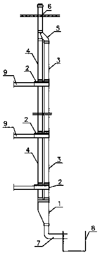
[0042] Such as figure 1 As shown, a novel double riser drainage system includes a drainage riser 4 and an aeration riser 3 arranged side by side, and the tops of the top drainage riser 4 and the aeration riser 3 are connected to the roof extension pipe 6 through a top junction 5 The bottom of the bottom drainage riser 4 and the ventilation riser 3 are connected to the drain pipe 7 through the bottom junction 1, the drain pipe 7 is connected to the inspection well 8, and the drainage lateral branch pipe 9 is connected to the water-gas separation module 2.

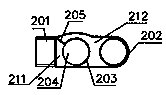
[0043] Such as figure 2 and image 3 As shown, the water-gas separation module 2 includes a closed cavity, the top of the closed cavity is provided with the upper connecting pipe 203 of the drainage standpipe and the upper connecting pipe 202 of the ventilation standpipe, and the bottom of the closed cavity is provided with the lower connecting pipe 206 of the drainage standpipe and the ventilation standpipe. The lower co...

Embodiment 2

[0050] A new double-standpipe drainage system. The difference between this embodiment and Embodiment 1 is that the water-air separation module 2 is patented as "a side vertical reclaimed water storage, treatment, reuse and discharge for toilets." System (Application No.: 201810149057.6)” for the core module 10 (the core module 10 in the above-mentioned patent application), the drainage lateral branch pipe 9 is directly connected to the drainage socket on the core module 10.

Embodiment 3

[0052] Such as Figure 6 As shown, a new type of double-standpipe drainage system, the difference between this embodiment and the first embodiment is that the ventilation riser socket 13 and the drainage riser socket 14 of the bottom junction 1 protrude from the top surface of the housing, and the partition 17 top is located at the top of housing 11.


PUM


Abstract

The invention discloses a novel double-vertical-pipe water discharging system, and belongs to the technical field of a building indoor water discharging system. Through a water vapor separation module, water and gas in a water discharging transverse support pipe are respectively communicated with a water discharging vertical pipe and a ventilation vertical pipe, so that a water seal device communicated with the water discharging transverse branch pipe cannot be influenced by the gas pressure fluctuation of the water discharging vertical pipe; a water vapor separation and gas circulation waterdischarging system is formed; the circulation supplementation of gas in the water discharging vertical pipe is favorably realized; the gas pressure balance in the water discharging vertical pipe is stabilized; the smooth discharging of water flow in the water discharge vertical pipe is ensured; the water discharging capability is improved; the ventilation process and realization path of a conventional H type communication double-vertical-pipe water discharging system are fundamentally changed; the problems that the water discharging transverse pipe and the water discharging vertical pipe are communicated in a sealed way, the indirect communication mode of the water discharging vertical pipe and the ventilation pipe H connecting pipe is used, so that the odor returns from a floor drain canbe solved; meanwhile, the technical problem that the ventilation pipe or the annular ventilation pipe of the existing device is singly communicated with the ventilation vertical pipe, so that the surface mounting is needed is also solved.

Description

technical field [0001] The invention relates to the technical field of building indoor drainage systems, in particular to a novel double riser building indoor drainage system. Background technique [0002] At present, there are three types of indoor drainage systems in buildings: the first is the drainage system below the ninth floor, which adopts the roof ventilating pipe for drainage, and there is no need to set up a special ventilation pipe; Special ventilation pipes, and require H-shaped pipes to be connected layer by layer or interlayer between the special ventilation pipes and the drainage standpipe. The sewage in the drainage vertical pipe vertically spirals along the pipe wall, and it is easy to form inertia at the H-shaped connection opening. The water curtain or water film blocks the connecting vent pipe opening, causing water to enter the H-shaped connecting pipe and enter the vent pipe, affecting the ventilation of the vent pipe, and the water curtain blocks the ...

Claims


Application Information

Patent Timeline
Patent Type & Authority Applications(China)
IPC IPC(8): E03C1/122
CPCE03C1/122
Inventor 王凤蕊李希成贾晓艳王伟丽
Owner PUYANG OCTAVIA BUILDING ENERGY SAVING TECHOLOGY CO LTD
Why Eureka
Try Eureka