A single-side stacking type direct access parking device
A technology of a parking device and a stacking device, which is applied to the buildings, building types, buildings, etc. where cars are parked, can solve the problems of inapplicable community structure, cumbersome parking and retrieval process, and strict site requirements, so as to save the time for accessing cars. , The effect of flexible configuration and strong adaptability
- Summary
- Abstract
- Description
- Claims
- Application Information
AI Technical Summary
Problems solved by technology
Method used
Image
Examples
specific Embodiment approach 1
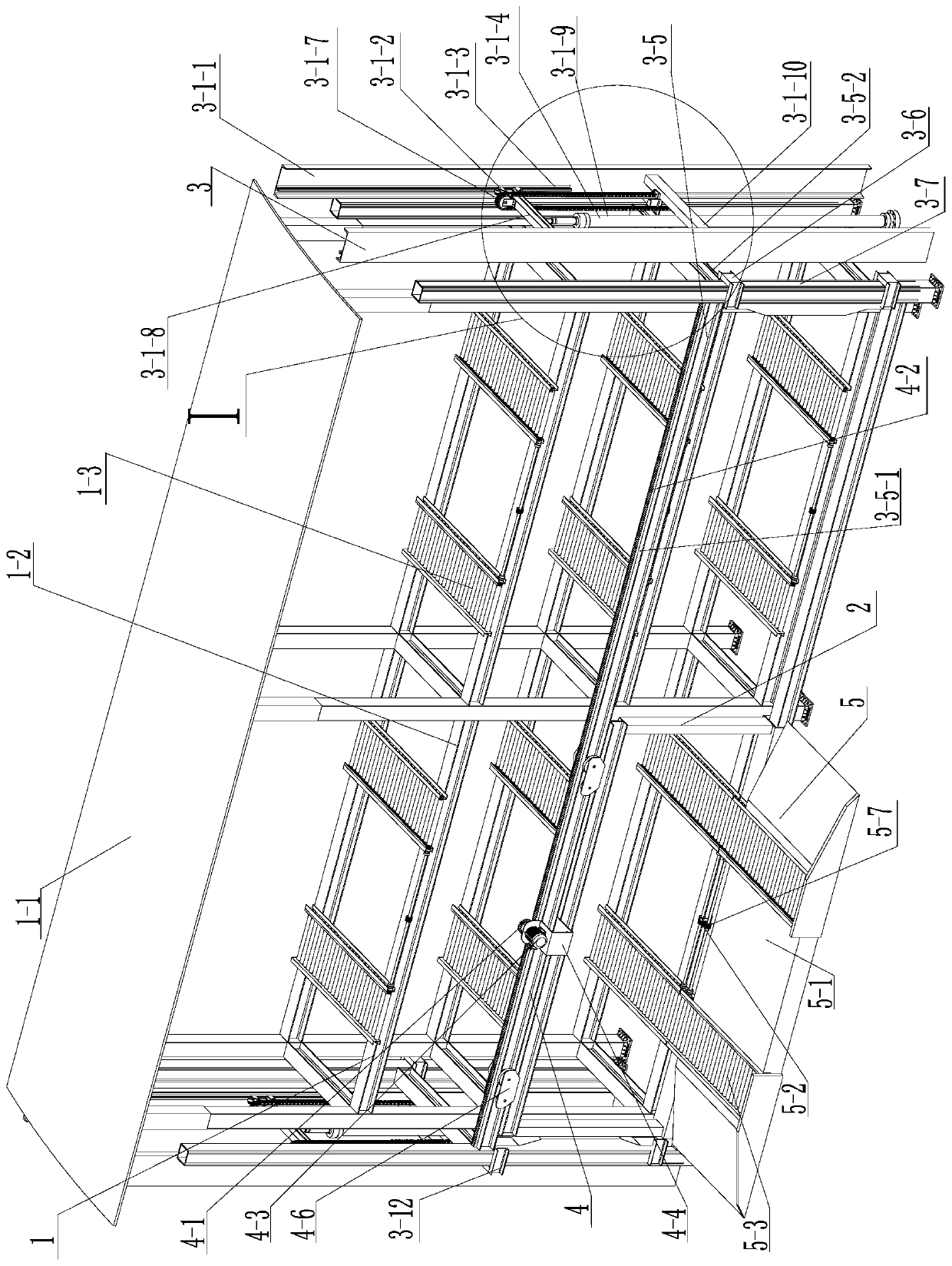
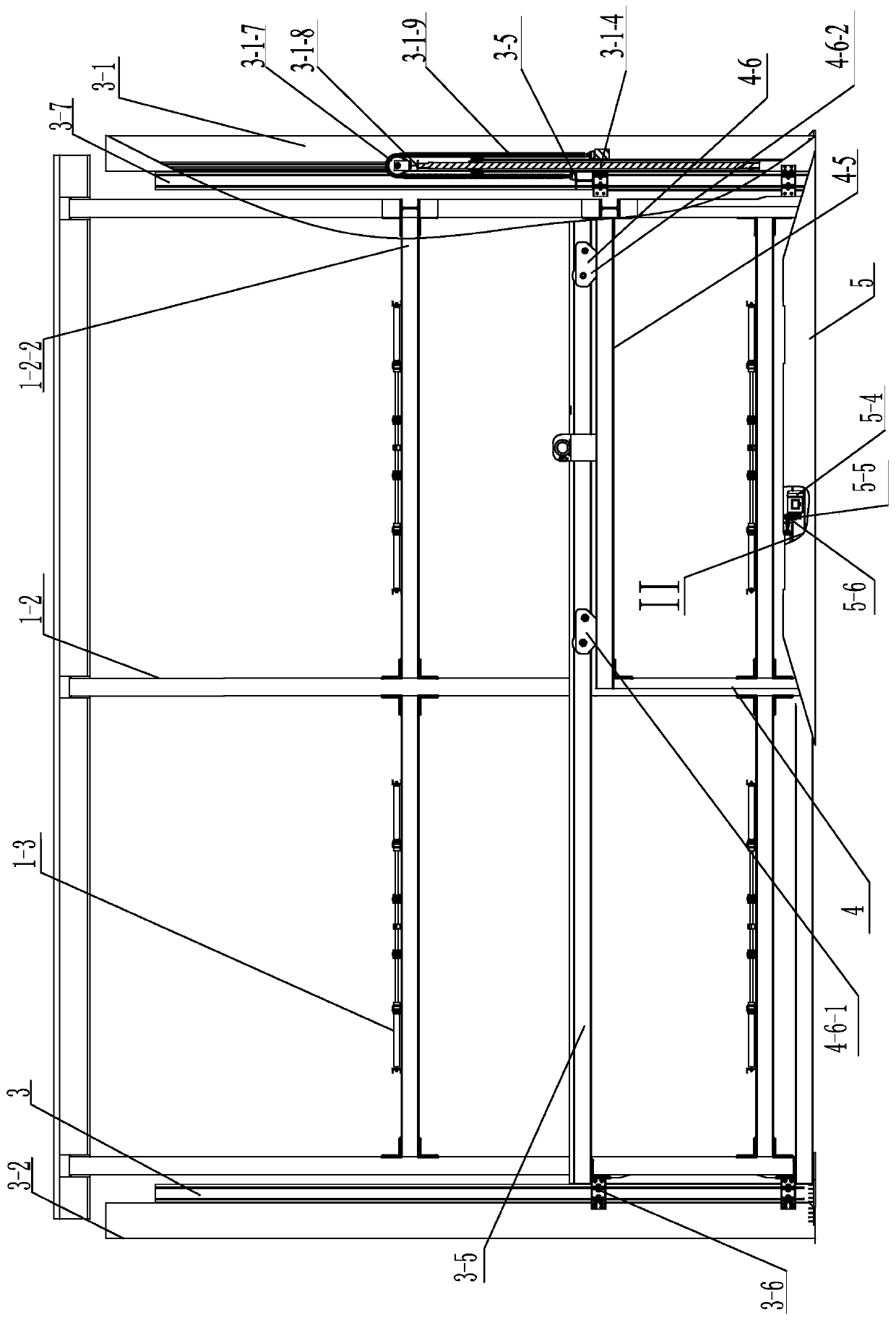
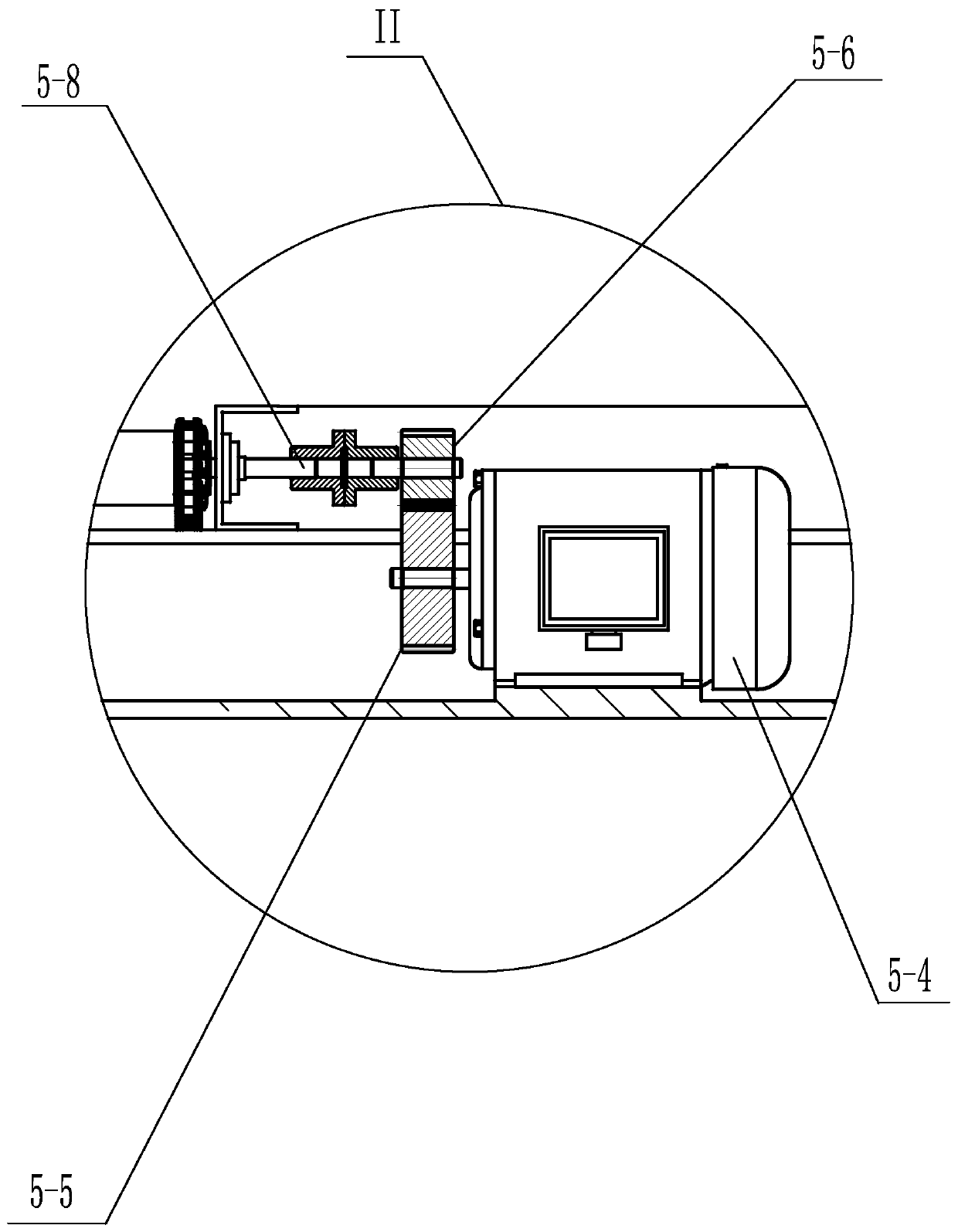
[0021] Specific implementation mode one: combine Figure 1-Figure 8 Describe this embodiment, it includes unilateral parking device 1 and unilateral stacking device 2 in this embodiment, it is characterized in that: described unilateral parking device 1 is used in conjunction with unilateral stacking device 2;
[0022] The unilateral parking device 1 comprises a main body frame 1-2 and a plurality of parking roller groups 1-3. The main body frame 1-2 is provided with a plurality of parking spaces, and the plurality of parking spaces are arranged in an array from bottom to top. The bottom of each parking space A parking roller group 1-3 is installed on it, and the unilateral stacking device 2 includes a longitudinal moving assembly 3, a lateral moving assembly 4 and a public vehicle carrying device 5,
[0023] Public vehicle-carrying device 5 is positioned at the side of lateral movement assembly 4, and public vehicle-carrying device 5 is detachably connected with lateral movem...
specific Embodiment approach 2
[0025] Specific implementation mode two: combination figure 1 , figure 2 and Figure 4 To illustrate this embodiment, each parking roller group 1-3 in this embodiment includes a parking meshing gear 1-3-2, a drive shaft 1-3-3, two couplings 1-3-4, two roller rows 1-3-1 and two roller chains 1-3-5, multiple rollers in each roller row 1-3-1 are connected by roller chain 1-3-5, each roller row 1-3- The first roller in 1 is the driving roller, the transmission shaft 1-3-3 is installed between the driving rollers of the two parking roller rows 1-3-1, and one end of the transmission shaft 1-3-3 passes through the coupling 1 -3-4 is connected with the driving roller of a parking roller row 1-3-1, and the other end of the transmission shaft 1-3-3 is connected with another parking roller row 1-3-1 through a coupling 1-3-4 The driving roller is connected, and the parking meshing gear 1-3-2 is set on the middle part of the transmission shaft. Other compositions and connections are t...
specific Embodiment approach 3
[0026] Specific implementation mode three: combination figure 1 , figure 2 , Figure 4 and Figure 7 To illustrate this embodiment, the longitudinal movement assembly 3 of this embodiment includes a longitudinal movement pulley block 3-6, a longitudinal movement frame 3-5, a longitudinal movement column 3-7, and components composed of the same left lifting member 3-1 and right lifting member 3- 2,
[0027] The left lifting part 3-1 and the right lifting part 3-2 are symmetrically arranged on the left and right sides of the unilateral parking device 1, and four longitudinally moving columns 3-7 are arranged on the left lifting part 3-1, the right lifting part 3-2 and the left lifting part 3-2. The position in the middle of the unilateral parking device 1, four vertically moving columns 3-7 are slidably connected with the longitudinally moving frame 3-5 through the longitudinally moving pulley block 3-6, and each left elevating part 3-1 and right elevating part 3-2 are It i...
PUM
 Abstract
Description
Claims
Application Information
 - R&D
- Intellectual Property
- Life Sciences
- Materials
- Tech Scout
- Unparalleled Data Quality
- Higher Quality Content
- 60% Fewer Hallucinations
Browse by: Latest US Patents, China's latest patents, Technical Efficacy Thesaurus, Application Domain, Technology Topic, Popular Technical Reports.
© 2025 PatSnap. All rights reserved.Legal|Privacy policy|Modern Slavery Act Transparency Statement|Sitemap|About US| Contact US: help@patsnap.com


