
A propulsion device and propulsion method for a space maneuvering platform

A maneuvering and platform technology, applied in jet propulsion devices, thrust reversers, rocket engine devices, etc., can solve the problems of immature space nuclear power supply technology, increase labor costs, offset fuel economy, etc. Scope of rapid rail change requirements, the effect of reducing fuel consumption and power consumption

Active Publication Date: 2019-08-09
XIAN INSTITUE OF SPACE RADIO TECH
View PDF11 Cites 0 Cited by
  • Summary
  • Abstract
  • Description
  • Claims
  • Application Information

AI Technical Summary

Problems solved by technology

For tasks such as rapid orbit transfer and deep-space manned exploration that have strict requirements on mission time, the low-thrust electric propulsion system performs poorly. It generally takes more than 100 days for an orbit transfer, which not only greatly reduces the cost of satellite investment. Real-time, which offsets the economy brought by saving fuel, and at the same time puts forward higher requirements on issues such as measurement and control during the transfer process, which greatly increases labor costs
However, high-power electric propulsion systems, such as magnetoplasma thrusters and helicon wave plasma thrusters, can achieve greater thrust and higher specific impulse, but the power consumption will reach an astonishing megawatt level
Measured by the power supply capacity of space solar energy at present and in the next few years, it is far from meeting the power supply needs of this type of high-power electric propulsion system. In the future, it can only rely on space nuclear energy power supply, but the current space nuclear energy power supply technology is still very immature
Therefore, it is difficult for high-power pure electric propulsion systems to be applied in space in the short term

Method used


Image

  • A propulsion device and propulsion method for a space maneuvering platform
  • A propulsion device and propulsion method for a space maneuvering platform
  • A propulsion device and propulsion method for a space maneuvering platform

Examples


Embodiment

[0082] (1) Theoretical comparison between the present invention and traditional chemical propulsion method

[0083] The energy for chemical propulsion comes from the chemical energy released by chemical reactions. Under the same mass of working fluid, the more chemical energy released, the greater the specific impulse that chemical propulsion can achieve theoretically. With hydrogen (H 2 ) as fuel, oxygen (O 2 ) as an oxidizing agent, under the traditional chemical propulsion method, 1mol H 2 and 0.5mol O 2 A complete chemical combustion reaction occurs to generate 1 mol of water vapor (H 2 O) the energy released is about 245kJ, and the energy equation is:

[0084] h 2 (g)+0.5O 2 (g)→H 2 O(g)-245kJ / mol.

[0085] The chemical energy released by the direct chemical combustion reaction of H and O atoms to generate 1 mol of water vapor is about 930KJ, and the energy equation is:

[0086] 2H(g)+O(g)→H 2 O(g)-930kJ / mol.

[0087] If the propulsion method in the present in...


PUM


Abstract

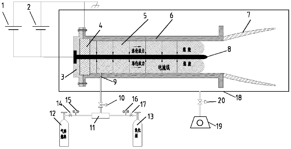
The invention relates to a propelling device and method for a space maneuvering platform and belongs to the technical field of space propelling. The propelling method is a composite propelling methodwith chemical propelling and electric propelling combined. The propelling device for the space maneuvering platform is provided, and the new composite propelling method is formed by combining chemicalpropelling and electric propelling processes. The chemical propelling process is that a combustible gas working medium mixture is ionized and ignited under the effect of high-voltage pulses, a chemical combustion reaction is induced, a large amount of chemical energy is released, thus mixed gas expansion is accelerated, and forward thrust is provided for the device owing to resisting of a front end thrust wall; and the electric propelling process is that a plasma mixture generated by ionization and the chemical combustion reaction is accelerated backwards under the Lorentz force effect generated by the mutual effect of a large current and an induced magnetic field of the plasma mixture and is sprayed out through an exhaust nozzle to provide forward thrust for the whole device.

Description

technical field [0001] The invention relates to a propulsion device and a propulsion method for a space maneuvering platform, belonging to the field of space propulsion technology, and the method is a compound propulsion method combining chemical propulsion and electric propulsion. Background technique [0002] As a kind of orbit transfer vehicle, the space maneuvering platform can carry a variety of payloads and deliver them to different orbits to act on different space targets. In order to improve the timeliness and multi-target capability of space maneuvering, the space maneuvering platform is required to have the ability to quickly change orbits and multiple orbits in a wide range, which puts forward an urgent demand for space thrusters with high thrust and high specific impulse. [0003] According to different energy sources and conversion methods, current space propulsion types are mainly divided into chemical propulsion and non-chemical propulsion. Among them, the th...

Claims


Application Information

Patent Timeline
Patent Type & Authority Patents(China)
IPC IPC(8): F03H1/00F02K9/42F02K9/44
CPCF02K9/42F02K9/44F03H1/0087
Inventor 方进勇王效顺黄惠军彭凯张颖军
Owner XIAN INSTITUE OF SPACE RADIO TECH
Learn More