Rotation type self-adaption magnetorheological fluid damper

A magneto-rheological fluid and self-adaptive technology, applied in the field of structural vibration control and rotary self-adaptive magneto-rheological fluid shock absorbers, can solve problems such as inability to achieve vibration reduction effects, and achieve good applicability and economy, Controllable and adaptable effects

Active Publication Date: 2018-11-23
SHANDONG UNIV
View PDF6 Cites 2 Cited by
  • Summary
  • Abstract
  • Description
  • Claims
  • Application Information

AI Technical Summary

Problems solved by technology

Most of the magneto-rheological shock absorbers currently used are mainly piston rod type. If they cannot have a l

Method used


Image

  • Rotation type self-adaption magnetorheological fluid damper
  • Rotation type self-adaption magnetorheological fluid damper
  • Rotation type self-adaption magnetorheological fluid damper

Examples


Embodiment 1

[0040] In a typical implementation of the present application, a rotary adaptive magnetorheological fluid shock absorber has only one layer, which includes a cylinder, which is divided into a vibration excitation layer and a magnetorheological damping layer; A full-length fixed shaft is installed inside the cylinder, and a rotating shaft is set outside the fixed shaft. The bottom end of the rotating shaft is extended to form a chassis, and a universal ball joint is set at the bottom of the chassis, which is placed in the magnetorheological fluid storage chamber. A circle of universal spherical hinges is respectively arranged on the inner side of the upper and lower ends of the rotating shaft, and the fan blade and the rotating disc are fixed on the rotating shaft.

[0041] The vibration excitation layer includes two mass blocks. A roller is arranged at the bottom of the mass blocks. One end of the mass blocks is connected to the inner wall of the barrel by a spring, and the oth...

Embodiment 2

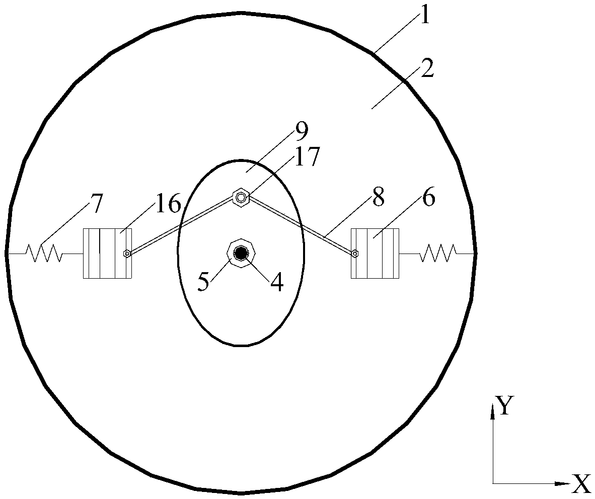
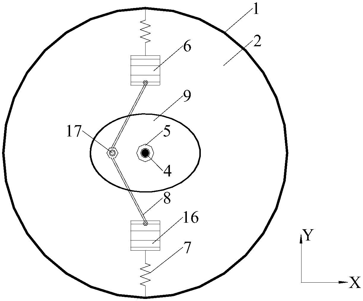
[0048] Such as figure 1 As shown, the rotary adaptive magnetorheological fluid shock absorber includes two layers. There are two vibration excitation layers 2 and two magnetorheological damping layers 3 respectively. The vibration excitation layer 2 and the magnetorheological damping layer 3 mainly control the vibration in the Y direction, the lower layer mainly controls the vibration in the X direction, and the vibration excitation layer 2 that controls vibration in the same direction is above the magnetorheological damping layer 3, and the circuit control room 13 It is only distributed inside the magnetorheological damping layer 3 .

[0049] Specifically, it includes a cylinder 1, and the cylinder 1 is divided into an upper part and a lower part; the upper part includes a vibration excitation layer 2 and a magnetorheological damping layer 3; the lower part also includes a vibration excitation layer 2 and a magnetorheological damping layer 3;

[0050] A full-length fixed sha...


PUM


Abstract

The invention discloses a rotation type self-adaption magnetorheological fluid damper. The rotation type self-adaption magnetorheological fluid damper comprises a cylinder and is characterized in thatthe cylinder is divided into vibration excitation layers and magnetorheological damping layers, an elongated fixed shaft is arranged inside the cylinder, and a rotary shaft is arranged outside the fixed shaft and can freely rotate around the fixed shaft; each vibration excitation layer is provided with two mass blocks which can move in one direction; one end of each mass block is connected with the inner wall of the cylinder through a spring, and the other end of each mass block is connected with a limit bearing inside a rotary disc through a connecting rod; each magnetorheological damping layer is provided with a built-in magnetorheological fluid storage cavity, and two excitation coils are arranged on each of the upper surface and the lower surface of the magnetorheological fluid storage cavity; the excitation coils are connected into a circuit control chamber on the periphery of the corresponding magnetorheological fluid storage cavity; blades are arranged inside the magnetorheological fluid storage cavities and connected with the rotary shaft.

Description

technical field [0001] The invention belongs to the field of vibration control of construction engineering, in particular to a rotary self-adaptive magnetorheological fluid shock absorber, which is mainly used in the vibration control of structures such as super high-rise buildings and large spans. technical background [0002] Structural vibration control technology has changed the traditional design ideas of civil engineering in the past. Vibration damping devices are used to control the dynamic response of the structure itself to achieve the purpose of suppressing bad vibration of the structure. Among them, the semi-active control uses sensitive materials to sense the external excitation and structural vibration response information, and changes the parameters of the structure in real time through adaptive stiffness or damping of driving materials (such as shape memory materials, electrorheological materials, magnetorheological materials, etc.), Realize dynamic control to...

Claims


Application Information

Patent Timeline
IPC IPC(8): F16F9/53
CPCF16F9/53F16F2224/045F16F2228/066
Inventor 田利周梦瑶陈城高国栋
Owner SHANDONG UNIV
Why Eureka
Try Eureka