Residual stress nondestructive testing system and method based on transient grating laser ultrasonic surface wave

A technology of laser ultrasound and residual stress, applied in force/torque/work measuring instruments, measuring devices, material analysis through optical means, etc., can solve the problems of poor spatial resolution and low precision, and achieve high anti-noise ability, Effect of High Sensitivity and Spatial Resolution

Active Publication Date: 2018-11-23
XI AN JIAOTONG UNIV
View PDF9 Cites 17 Cited by
  • Summary
  • Abstract
  • Description
  • Claims
  • Application Information

AI Technical Summary

Problems solved by technology

[0005] In order to solve the main shortcomings of the current ultrasonic residual stress detection method such as low precision and poor spatial resolution, the purpose of the present invention is to propose a non-destructive detection system and method for residual stress based on transient grating laser ultrasonic surface waves

Method used


Image

  • Residual stress nondestructive testing system and method based on transient grating laser ultrasonic surface wave
  • Residual stress nondestructive testing system and method based on transient grating laser ultrasonic surface wave
  • Residual stress nondestructive testing system and method based on transient grating laser ultrasonic surface wave

Examples


Embodiment Construction

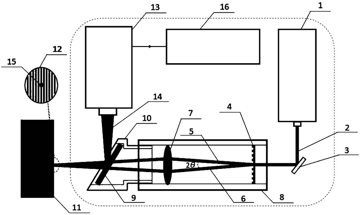
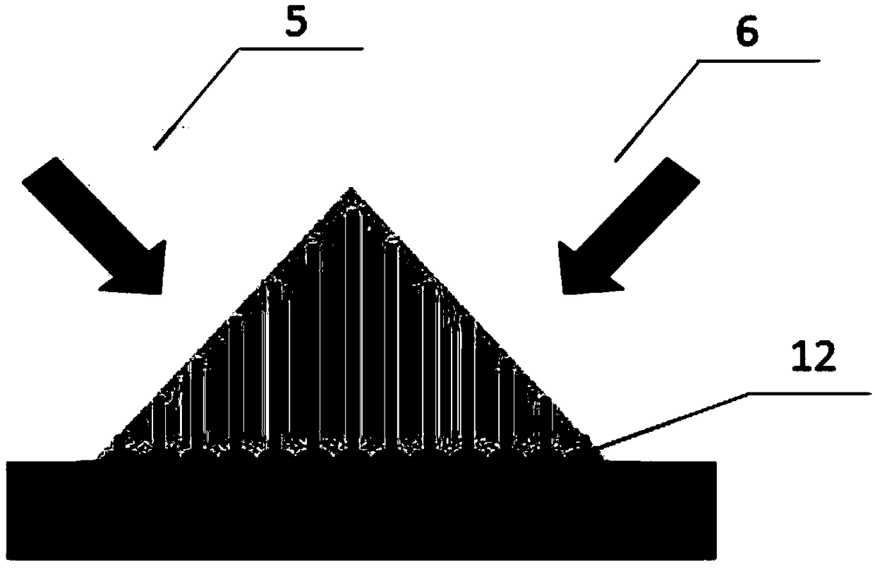
[0026] Such as figure 1As shown, the residual stress non-destructive testing system based on transient grating laser ultrasonic surface wave, the system includes a pulsed laser 1, a mirror 3, a phase grating beam splitter 4, an imaging lens 7, a dichromatic mirror 9, and a circular lens barrel 8 , a 45-degree cylindrical mount 10, a laser interferometer 13, and a signal acquisition and processing unit 16; the reflector 3 is positioned so that the pulsed laser beam 2 generated by the pulsed laser 1 is reflected by the reflector 3 and then vertically incident on the phase On the grating beam splitter 4, the sub-laser beam exit end of the phase grating beam splitter 4 is placed with an imaging lens 7, a dichromatic mirror 9 and a test piece 11 in sequence, and the first sub-laser beam 5 formed by the phase grating beam splitter 4 and The second sub-laser beam 6 forms interference fringes 12 on the surface of the test piece 11 after passing through the imaging lens 7 and the dichr...


PUM


Abstract

The present invention discloses a residual stress nondestructive testing system and method based on a transient grating laser ultrasonic surface wave. A laser beam generated by a pulse laser passes through a phase grating beam splitter and an imaging lens to form two laser sub-beams which intersect at a certain angle and irradiate the surface of a test sample to generate interference fringes witha fixed cycle [Lambda], and two coherent surface waves with wavelengths of [Lambda] propagated at two opposite directions are excited at the surface of the test sample under the action of the cycle hot elastic force; a laser interferometer is employed to receive generated surface wave signals generated at the excitation position to perform Fourier transform of the received signals to obtain a center frequency f, and a propagation velocity c of the surface wave of the detected position is calculated according to a formula of c=f*[Lambda]; and finally, a relative change amount of the wave speedof the surface wave is finally obtained in a condition of different stresses relative to the wave speed of the surface wave in a condition without stress to obtain a linear relation between the relative change amount of the wave speed of the surface wave and the stresses, and based on the linear relation, the wave speed of the surface wave propagated at the test sample surface in an unknown stressstate is measured through the method mentioned above to determine the magnitude of the stresses of the test sample surface.

Description

technical field [0001] The invention relates to a nondestructive detection method for residual stress, in particular to a nondestructive detection method for residual stress based on transient grating laser ultrasonic surface waves. Background technique [0002] Some important structures in the mechanical system are prone to microscopic damage such as residual stress and strain on the surface and interior of the structure when they are subjected to excessive loads during processing, assembly and operation. The existence of these microscopic damages will not only greatly reduce the mechanical properties of the structure, but also easily cause macroscopic damages such as stress corrosion cracks and fatigue cracks in the structure, which poses a great hidden danger to the safety of the mechanical structure. [0003] Currently applied residual stress measurement methods can be divided into two categories: destructive and nondestructive. The destructive test method refers to the...

Claims


Application Information

Patent Timeline
Patent Type & Authority Applications(China)
IPC IPC(8): G01L5/00G01N21/17
CPCG01L5/0047G01N21/1702G01N2021/1706
Inventor 裴翠祥寇兴弋东驰刘天浩
Owner XI AN JIAOTONG UNIV
Why Eureka
Try Eureka