Method and system for detecting and positioning micro-cracks based on ultrasonic phased array

A technology of ultrasonic phased array and positioning method, which is applied in the direction of using sound wave/ultrasonic wave/infrasonic wave to analyze solids and process detection response signals. The effects of improved detection and positioning accuracy, high detection and positioning accuracy, high recognition rate and accuracy

Active Publication Date: 2018-11-23
WUHAN INSTITUTE OF TECHNOLOGY
View PDF6 Cites 6 Cited by
  • Summary
  • Abstract
  • Description
  • Claims
  • Application Information

AI Technical Summary

Problems solved by technology

[0003] At present, the research on micro-crack detection almost stays at the linear acoustic level, and it is impossible to effectively detect micro-cracks. The detection of micro-cracks must use nonlinear ultrasonic technology, such as vibration-acoustic modulation technology. The detection is very sensitive and can accurately determine whether there are micro-cracks in the structure
However, the current nonlinear ultrasonic technology can only detect the surface of the structure, let alone make an effective judgment on the location of the micro-cracks, and the detection of the structure is mainly for thin metal sheet structures such as aluminum tubes. The detection and positioning of thicker structures cannot show high recognition rate and accuracy, and cannot be extended to a wider field of micro-crack detection

Method used


Image

  • Method and system for detecting and positioning micro-cracks based on ultrasonic phased array
  • Method and system for detecting and positioning micro-cracks based on ultrasonic phased array
  • Method and system for detecting and positioning micro-cracks based on ultrasonic phased array

Examples


Embodiment 1

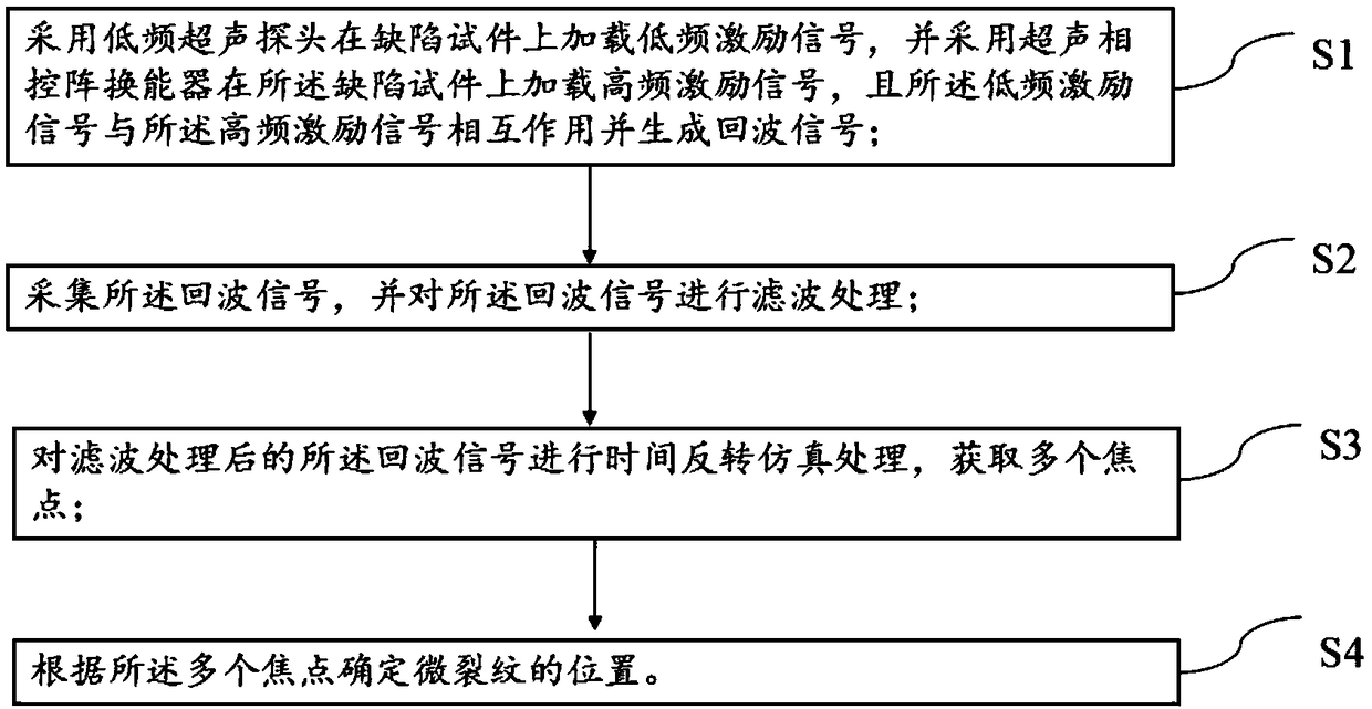
[0057] Embodiment one, as figure 1 As shown, it is a micro-crack detection and location method based on ultrasonic phased array of the present invention, comprising the following steps:

[0058] S1: Sampling a low-frequency ultrasonic probe to load a low-frequency excitation signal on the defect test piece, and using an ultrasonic phased array transducer to load a high-frequency excitation signal on the defect test piece, and the low-frequency excitation signal and the high-frequency excitation signal The signals interact and generate an echo signal;

[0059] S2: collecting the echo signal, and performing filtering processing on the echo signal;

[0060] S3: Perform time-reversal simulation processing on the filtered echo signal to obtain multiple focal points;

[0061] S4: Determine the position of the micro-crack according to the multiple focal points.

[0062] In this embodiment, an ultrasonic phased array based on vibration-acoustic modulation is used to excite high-fre...

Embodiment 2

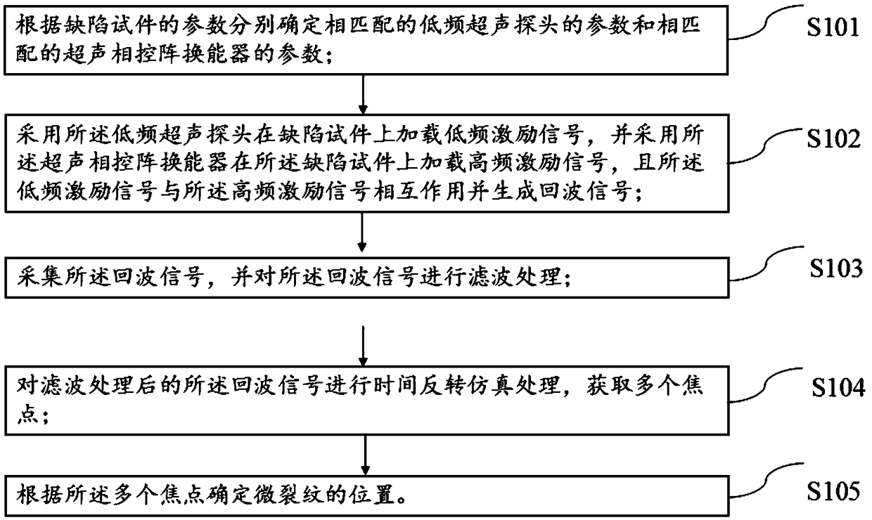
[0063] Embodiment two, such as figure 2 Shown is another embodiment of a micro-crack detection and location method based on ultrasonic phased array of the present invention, comprising the following steps:

[0064] S101: Determine the matched parameters of the low-frequency ultrasonic probe and the ultrasonic phased array transducer respectively according to the parameters of the defective test piece.

[0065] In this embodiment, a carbon steel plate with a length of 200 mm, a width of 200 mm, and a thickness of 20 mm is selected as a defect test piece, and the defect test piece contains a microcrack inside. In this steel plate, the propagation velocity of the transverse wave is 3200m / s, and the propagation velocity of the longitudinal wave is 5900m / s, so it is determined that the center frequency of the low-frequency ultrasonic probe in this embodiment is 0.5MHz, and the sampling frequency is 100MHz. The transducer contains 64 vibration elements, and the center frequency of...

Embodiment 3

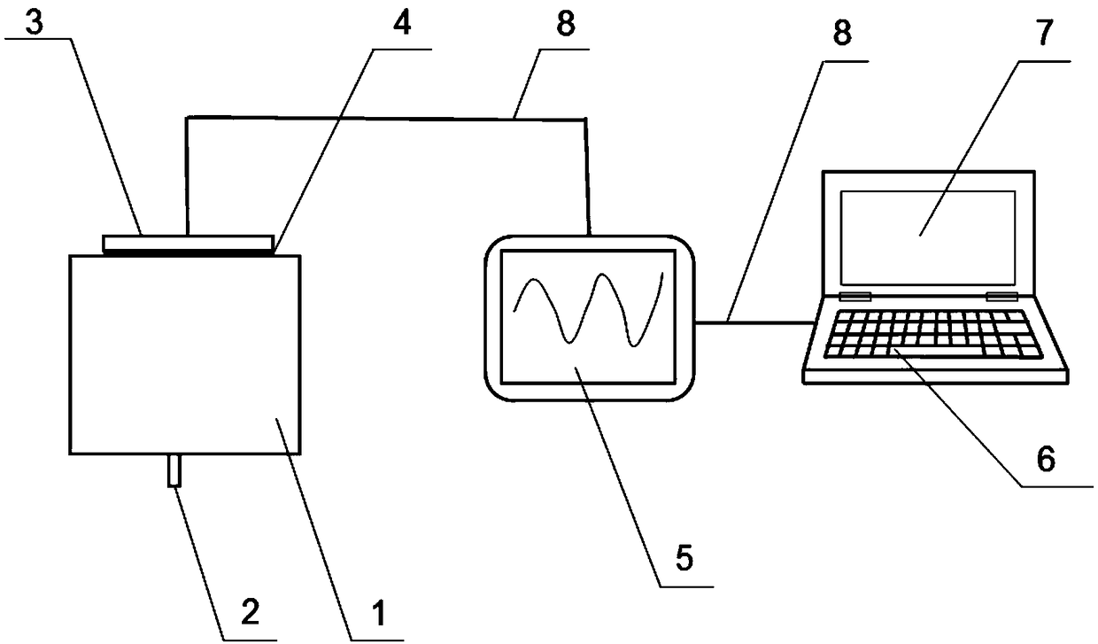
[0090] Embodiment three, as image 3 As shown, it is a structural schematic diagram of a micro-crack detection and positioning system based on ultrasonic phased array of the present invention, including a defect test piece 1, a low-frequency ultrasonic probe 2, an ultrasonic phased array transducer 3, a signal acquisition device 5, Processor 6;

[0091] The low-frequency ultrasonic probe 2 is arranged under the defect test piece 1 and faces the defect test piece 1, and the low-frequency ultrasonic probe 2 is used to load a low-frequency excitation signal on the defect test piece 1; the ultrasonic phase The controlled array transducer 3 is arranged above the defect test piece 1 and facing the defect test piece 1, and the ultrasonic phased array transducer 3 is used to load the high frequency excitation signal on the defect test piece 1 ; The signal acquisition device 5 is electrically connected with the low-frequency ultrasonic probe 1 and the ultrasonic phased array transduce...


PUM


Abstract

The invention relates to a method and a system for detecting and positioning micro-cracks based on an ultrasonic phased array. The method comprises the following steps of loading a low-frequency excitation signal onto a defect specimen by a low-frequency ultrasonic probe, loading a high-frequency excitation signal onto a defect specimen by an ultrasonic phased array transducer, and enabling the low-frequency excitation signal and the high-frequency excitation signal to mutually act and generate an echo signal; collecting the echo signal, and filtering the echo signal; performing time reversalsimulation treatment on the filtered echo signal, so as to obtain a plurality of focus points; according to the multiple focus points, determining the position of the micro-crack. The method has the advantages that the phased array technique, the vibration sound modulation and the time reversal are combined, so as to provide the method and the system for detecting and positioning the micro-cracks;the system and the method can be widely applied to the detection and positioning of the micro-cracks in the structures of different types; the identification rate and precision are higher, and the universality is high.

Description

technical field [0001] The invention relates to the field of non-destructive testing, in particular to a method and system for detecting and locating micro-cracks based on an ultrasonic phased array. Background technique [0002] In industry, structures often produce microcracks due to fatigue and other reasons. s consequence. Therefore, the detection of micro-cracks in the early stage of the structure is particularly important. [0003] At present, the research on micro-crack detection almost stays at the linear acoustic level, and it is impossible to effectively detect micro-cracks. The detection of micro-cracks must use nonlinear ultrasonic technology, such as vibration-acoustic modulation technology. The detection is very sensitive and can accurately determine whether there are micro-cracks in the structure. However, the current nonlinear ultrasonic technology can only detect the surface of the structure, let alone make an effective judgment on the location of the mic...

Claims


Application Information

Patent Timeline
Patent Type & Authority Applications(China)
IPC IPC(8): G01N29/04G01N29/07G01N29/12G01N29/44
CPCG01N29/04G01N29/07G01N29/12G01N29/44
Inventor 陈汉新曹承昊黄文健黄瑾珉杨柳方璐
Owner WUHAN INSTITUTE OF TECHNOLOGY
Why Eureka
Try Eureka