Temperature control device and method

A technology of temperature control device and temperature control method, which is applied in the direction of temperature control, non-electric variable control, control/regulation system, etc. It can solve the problems of parameter search without fixed means, swing, etc., and achieve stable, timely and efficient temperature control The effect of control

Inactive Publication Date: 2018-11-23
INST OF SEMICONDUCTORS - CHINESE ACAD OF SCI
View PDF5 Cites 8 Cited by
  • Summary
  • Abstract
  • Description
  • Claims
  • Application Information

AI Technical Summary

Problems solved by technology

The algorithm used in the traditional automatic temperature control circuit is the PID algorithm, which is the proportional, integral, and differential control algorithm. The disadvantage of this algorithm is that it needs to find the appropriate parameters to make the system quickly reach a stable state, and there is no fixed means to find the parameters. ; Second, even when a steady state is reached, the actual temperature will oscillate around the target temperature due to inherent flaws in the algorithm

Method used


Image

  • Temperature control device and method
  • Temperature control device and method

Examples


specific Embodiment 1

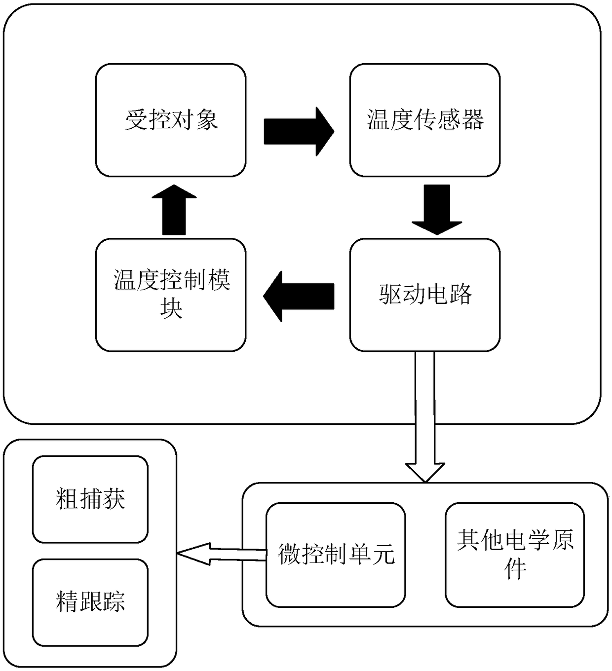
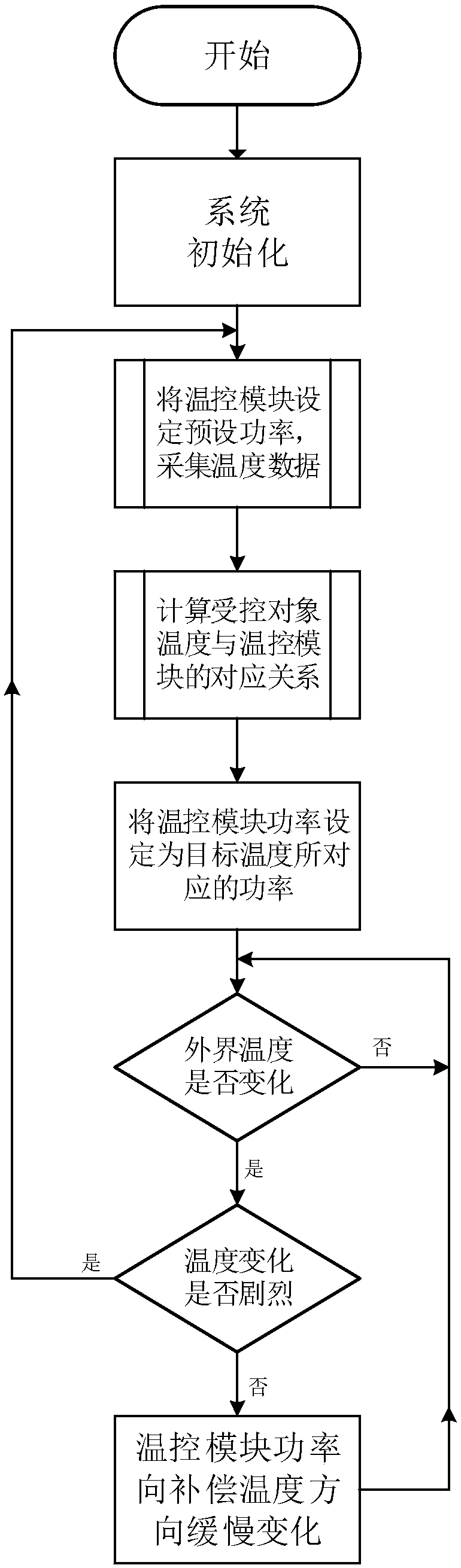
[0041] Take the work of semiconductor lasers as an example. In the actual work of semiconductor lasers, after the system is powered on and initialized, the temperature control module is first ordered to output several fixed powers, such as 10%, 15%, and 30% of full power. The processor records the corresponding laser temperature under these powers; uses the data collected by the temperature sensor to calculate the specific functional relationship between the output power of the temperature control module and the temperature of the laser in the current environment, and then calculates the output of the temperature control module required by the target temperature Power, through the output power of the temperature control module to directly make the laser reach the target temperature; the temperature sensor continues to monitor the laser temperature, if it is stable at the target temperature, the output power of the temperature control module remains unchanged, if the difference b...

specific Embodiment 2

[0042]Take the work of semiconductor lasers as an example. In the actual work of semiconductor lasers, after the system is powered on and initialized, the temperature control module is first ordered to output several fixed powers, such as 10%, 15%, and 30% of full power. The processor records the corresponding laser temperature under these powers; uses the data collected by the temperature sensor to calculate the specific functional relationship between the output power of the temperature control module and the temperature of the laser in the current environment, and then calculates the output of the temperature control module required by the target temperature power, directly make the laser reach the target temperature through the temperature control module; the temperature sensor continues to monitor the laser temperature, if it is stable at the target temperature, the output power of the temperature control module will not change, if the difference between the temperature and...


PUM


Abstract

The invention provides a temperature control device and method, and the device comprises a temperature sensor, a temperature control module, and a drive circuit. The drive circuit comprises a micro-control unit, other electrical elements, and a circuit design. A power-temperature function relation is written in the micro-control unit. In a current environment, the device directly enables a controlled object to reach a target temperature according to the function relation through set power. The device collects the temperature of the controlled object in real time through the temperature sensor,and transmits the collected temperature of the controlled object to the drive circuit. The drive circuit generates an adjustment instruction according to the power-temperature function relation through a temperature control algorithm, and transmits the adjustment instruction to the temperature control module, and the temperature control module enables the temperature to be constant through the power adjustment.

Description

technical field [0001] The invention relates to the field of automatic control, in particular to a temperature control device and a control method Background technique [0002] With the development of science and technology, more and more industrial and automation systems have more and more requirements for temperature control technology. At the same time, the accuracy and stability of temperature detection have become more and more important, such as the use of various high-tech places Electric heater protection unit, automatic fire alarm system, etc. The traditional temperature control system can realize the control of temperature detection and other aspects in the temperature control of a single product, but the current technological development has higher and higher requirements for batch detection of diversified products and linear adaptive control as the surrounding environment changes. . The algorithm used in the traditional automatic temperature control circuit is ...

Claims


Application Information

Patent Timeline
Patent Type & Authority Applications(China)
IPC IPC(8): G05D23/20
CPCG05D23/20
Inventor 齐艺超陈伟穆春元班德超祝宁华
Owner INST OF SEMICONDUCTORS - CHINESE ACAD OF SCI
Why Eureka
Try Eureka