Structure and method for improving double-grating coupling
A dual grating and grating technology, applied in the field of vacuum electronics, can solve the problems of difficult coupling of return wave tubes, low power radiation, and slow development of return wave tube applications, so as to increase the injection wave interaction space, improve power radiation, and enhance coupling effect
- Summary
- Abstract
- Description
- Claims
- Application Information
AI Technical Summary
Problems solved by technology
Method used
Image

Examples
Embodiment 1
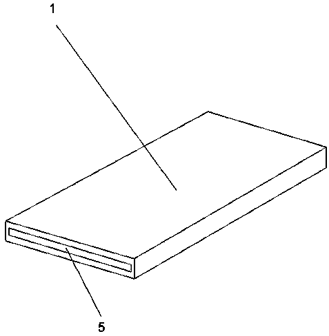
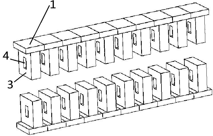
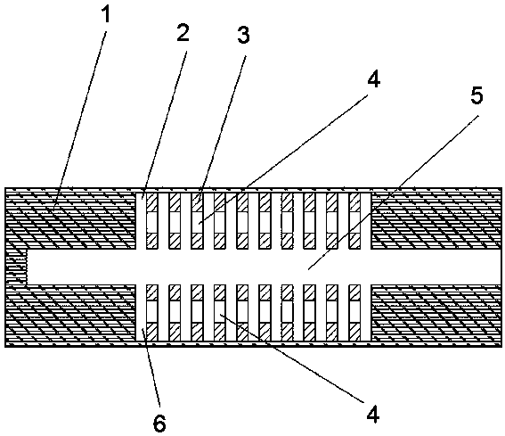
[0021] Such as figure 1 , figure 2 , image 3 and Figure 4 As shown, a structure for improving the coupling efficiency of double gratings includes a housing 1 and a plurality of grating columns 3. The housing 1 and the grating columns 3 can be made of materials such as gold, silver, copper, etc., and a channel 5 is arranged in the housing 1. The top is provided with a first groove 2, the bottom of the housing 1 is provided with a second groove 6, the opening of the first groove 2 and the opening of the second groove 6 are oppositely arranged; the first groove 2 and the second The grooves 6 are respectively located on the upper and lower sides of the channel 5; a plurality of the grating columns 3 are arranged at intervals in the first groove 2 and the second groove 6 respectively, and the bottom ends of the grating columns 3 are fixedly connected to the inner wall of the housing 1; Each grating column is provided with an opening 4, the grating column 3 is perpendicular to...
Embodiment 2
[0027] A method for improving the coupling efficiency of double gratings, which is applied to a structure for improving the coupling efficiency of double gratings, and can also be implemented independently. Openings 4 are arranged on the top, and electron beams are emitted from the front end of the channel 5 through the electron gun. The electromagnetic wave is coupled with the surface of the grating column 3 through the channel 5 to generate beam interaction. Since the multiple openings 4 form two new channels, an increase of The electric field coupling between the gratings enables the electron beam to interact more effectively with the grating structure, effectively improving the radiation efficiency, and finally the electron beam is output through the rear end of the channel 5.
[0028] In order to verify the effect of the present invention, this embodiment sets the observation point at the same position of the structure of the present invention and the existing double grati...
PUM
 Abstract
Description
Claims
Application Information
 - Generate Ideas
- Intellectual Property
- Life Sciences
- Materials
- Tech Scout
- Unparalleled Data Quality
- Higher Quality Content
- 60% Fewer Hallucinations
Browse by: Latest US Patents, China's latest patents, Technical Efficacy Thesaurus, Application Domain, Technology Topic, Popular Technical Reports.
© 2025 PatSnap. All rights reserved.Legal|Privacy policy|Modern Slavery Act Transparency Statement|Sitemap|About US| Contact US: help@patsnap.com