A structure and method for improving double grating coupling

A dual grating and grating technology, applied in the field of vacuum electronics, can solve the problems of difficult coupling of return wave tubes, low power radiation, and slow development of return wave tube applications, so as to increase the injection wave interaction space, improve power radiation, and enhance coupling effect

Active Publication Date: 2020-06-19
UNIV OF ELECTRONICS SCI & TECH OF CHINA
View PDF5 Cites 0 Cited by
  • Summary
  • Abstract
  • Description
  • Claims
  • Application Information

AI Technical Summary

Problems solved by technology

However, due to the characteristics of difficult coupling and low power radiation of the return wave tube in the high frequency band (terahertz band), the development of the application of the return wave tube in the high frequency band is extremely slow

Method used


Image

  • A structure and method for improving double grating coupling
  • A structure and method for improving double grating coupling
  • A structure and method for improving double grating coupling

Examples


Embodiment 1

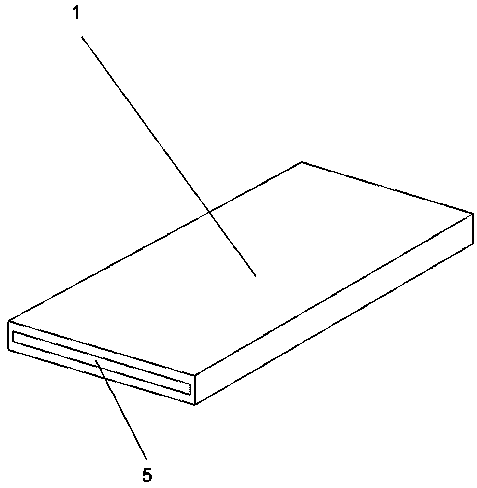
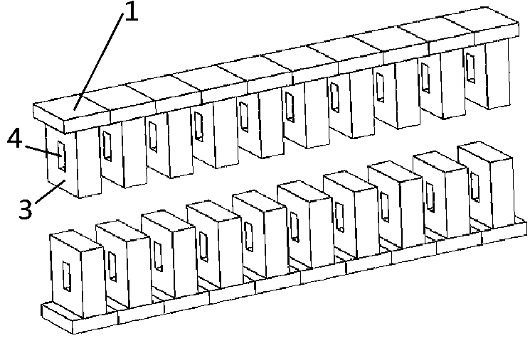
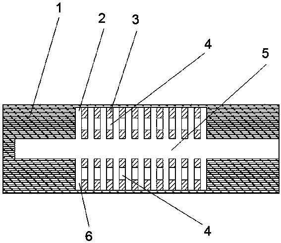
[0021] Such as figure 1 , figure 2 , image 3 and Figure 4 As shown, a structure for improving the coupling efficiency of double gratings includes a housing 1 and a plurality of grating columns 3. The housing 1 and the grating columns 3 can be made of materials such as gold, silver, copper, etc., and a channel 5 is arranged in the housing 1. The top is provided with a first groove 2, the bottom of the housing 1 is provided with a second groove 6, the opening of the first groove 2 and the opening of the second groove 6 are oppositely arranged; the first groove 2 and the second The grooves 6 are respectively located on the upper and lower sides of the channel 5; a plurality of the grating columns 3 are arranged at intervals in the first groove 2 and the second groove 6 respectively, and the bottom ends of the grating columns 3 are fixedly connected to the inner wall of the housing 1; Each grating column is provided with an opening 4, the grating column 3 is perpendicular to...

Embodiment 2

[0027] A method for improving the coupling efficiency of double gratings, which is applied to a structure for improving the coupling efficiency of double gratings, and can also be implemented independently. Openings 4 are arranged on the top, and electron beams are emitted from the front end of the channel 5 through the electron gun. The electromagnetic wave is coupled with the surface of the grating column 3 through the channel 5 to generate beam interaction. Since the multiple openings 4 form two new channels, an increase of The electric field coupling between the gratings enables the electron beam to interact more effectively with the grating structure, effectively improving the radiation efficiency, and finally the electron beam is output through the rear end of the channel 5.

[0028] In order to verify the effect of the present invention, this embodiment sets the observation point at the same position of the structure of the present invention and the existing double grati...


PUM


Abstract

The invention discloses a structure for improving the coupling efficiency of double gratings, which comprises a casing (1) and a plurality of grating columns (3), a channel (5) is arranged inside the casing (1), and a first grating is arranged above the casing (1). The groove (2), the second groove (6) is provided under the shell (1), the opening of the first groove (2) and the opening of the second groove (6) are oppositely arranged; the first groove ( 2) and the second groove (6) are respectively located on the upper and lower sides of the channel (5); a plurality of grating columns (3) are respectively arranged in the first groove (2) and the second groove (6) at intervals, and the grating The bottom end of the column (3) is fixedly connected with the inner wall of the casing (1); each grating column is provided with an opening (4), and the grating column (3) is perpendicular to the extending direction of the channel (5); The opening of the grating structure increases the beam-wave interaction space, effectively enhances the coupling between the electron beam and the grating, and improves the power radiation.

Description

technical field [0001] The invention relates to the technical field of vacuum electronics, in particular to a structure and method for improving double grating coupling. Background technique [0002] The return wave tube is an oscillator that self-excites and can generate electromagnetic wave oscillation with continuously adjustable frequency without the need for a signal. The core component in the return wave tube is the slow wave structure, and the double grating is a relatively common slow wave structure in the return wave tube. The electron beam emitted by the electron gun is coupled with the grating structure, and the injection wave interaction occurs. Because the return wave tube has the characteristics of broadband tuning, high power and high efficiency, it is suitable for applications such as radar and electronic interference, and can also be used as a driving source for other high-power microwave amplifiers. However, due to the characteristics of difficult coupling...

Claims


Application Information

Patent Timeline
Patent Type & Authority Patents(China)
IPC IPC(8): H01J23/24
CPCH01J23/24
Inventor 肖川红吴振华
Owner UNIV OF ELECTRONICS SCI & TECH OF CHINA
Why Eureka
Try Eureka