

Radiation detector with flash optical fiber
A radiation detector and scintillation fiber technology, applied in the field of radiation detectors, can solve the problems of low interaction probability, poor sensitivity and energy characteristics, large transmission loss of scintillation fiber, etc.
- Summary
- Abstract
- Description
- Claims
- Application Information
AI Technical Summary
Problems solved by technology
Method used
Image

Examples
Embodiment 1
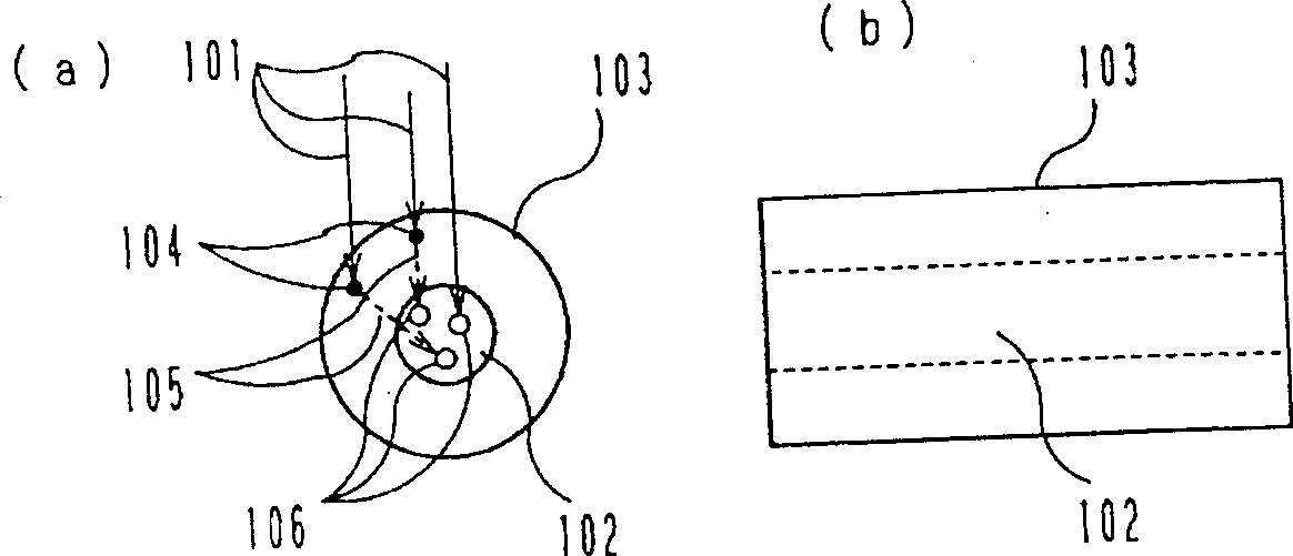
[0042] Embodiment 1 of the present invention will be described below with reference to the drawings. figure 1 The structure of the main part of the radiation detector according to Embodiment 1 of the present invention is schematically shown, wherein (a) is a cross-sectional structure diagram of a scintillation optical fiber, and (b) is a side structure diagram thereof. 101 in the figure is the measurement target radiation; 102 is the scintillation optical fiber, 103 is the scattering material that interacts with the radiation 101 to release electrons, 104 is the interaction point between the radiation 101 and the scattering material 103, and 105 is the interaction point The electrons or electrons and radiation rays released by 4, 106 are fluorescent spots generated due to the incident electrons or electrons and radiation rays.
[0043] The related work is explained below.
[0044] When the radiation 1 is incident into the radiation detector 101 with the above structure, it d...
Embodiment 2
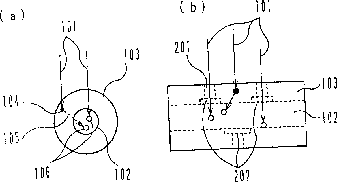
[0049] figure 2 The structure of the main part of the radiation detector of the second embodiment of the present invention is outlined. In Embodiment 1, there is no through hole in the scattering material 103 arranged around the scintillation optical fiber 102, but in Embodiment 2 as figure 2 Through-holes 201 are shown provided in the scattering material 103 . At this time, a light-shielding tape 202 is provided so that light does not directly enter the scintillation fiber 102 . Under such a structure, there is radiation 101 directly incident on the scintillation fiber. In addition to having the same effect as that of Embodiment 1, the range of sensitivity, energy characteristics and radiation dose rate can also be adjusted through the position of the fiber. According to this structure, high sensitivity and stable energy characteristics can be realized at the same time by combining a scattering material with a large atomic number.
Embodiment 3
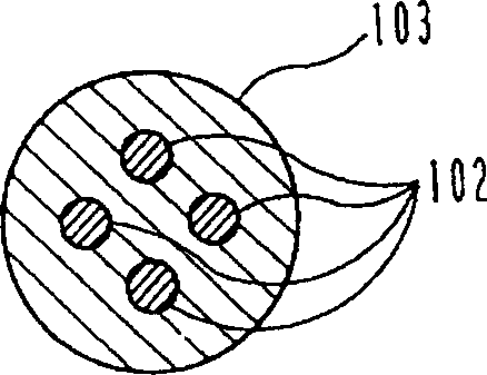
[0051] image 3 The main part of the radiation detector according to Embodiment 3 of the present invention is schematically shown in sectional view. Arranging multiple scintillation fibers 102 in the scattering material 103 can achieve the same effect as the above-mentioned embodiment 1, but the probability of radiation interacting with the scintillation fibers 102 can be further increased due to the arrangement of multiple scintillation fibers 102 . In addition, when a bundle of radiation interacts with the scintillation optical fiber 102 to generate fluorescence in multiple scintillation optical fibers, when the multiple scintillation optical fibers 102 are bundled and connected to a photodetector at one end or both ends respectively, it is possible to obtain The amount of light received is equivalent to one pulse, and the same effect of increasing the amount of fluorescence can be achieved.
PUM
 Abstract
Description
Claims
Application Information