Variable stiffness joint of flexible robot

A robot and variable stiffness technology, applied in the direction of manipulators, manufacturing tools, joints, etc., can solve the problems of non-compactness, continuous adjustment of output stiffness, complex structure of variable stiffness joints, etc., to achieve constant stiffness, easy installation and maintenance, The effect of controlling simplification

Active Publication Date: 2018-11-27
BEIJING PULIMEN ELECTRO MECHANICAL HIGH TECHN CO
View PDF8 Cites 14 Cited by
  • Summary
  • Abstract
  • Description
  • Claims
  • Application Information

AI Technical Summary

Problems solved by technology

[0006] The technical problem solved by the present invention is to provide a variable stiffness joint of a flexible robot, which can simulate the kinematic characteristics of the shoulder joint and elbow joint of the human arm, in view of the problems of the existing variable stiffness joint structure, which are complex and not compact, and the output stiffness cannot be continuously adjusted , effectively improving the safety and environmental adaptability of human-computer interaction

Method used


Image

  • Variable stiffness joint of flexible robot
  • Variable stiffness joint of flexible robot
  • Variable stiffness joint of flexible robot

Examples


specific Embodiment approach 1

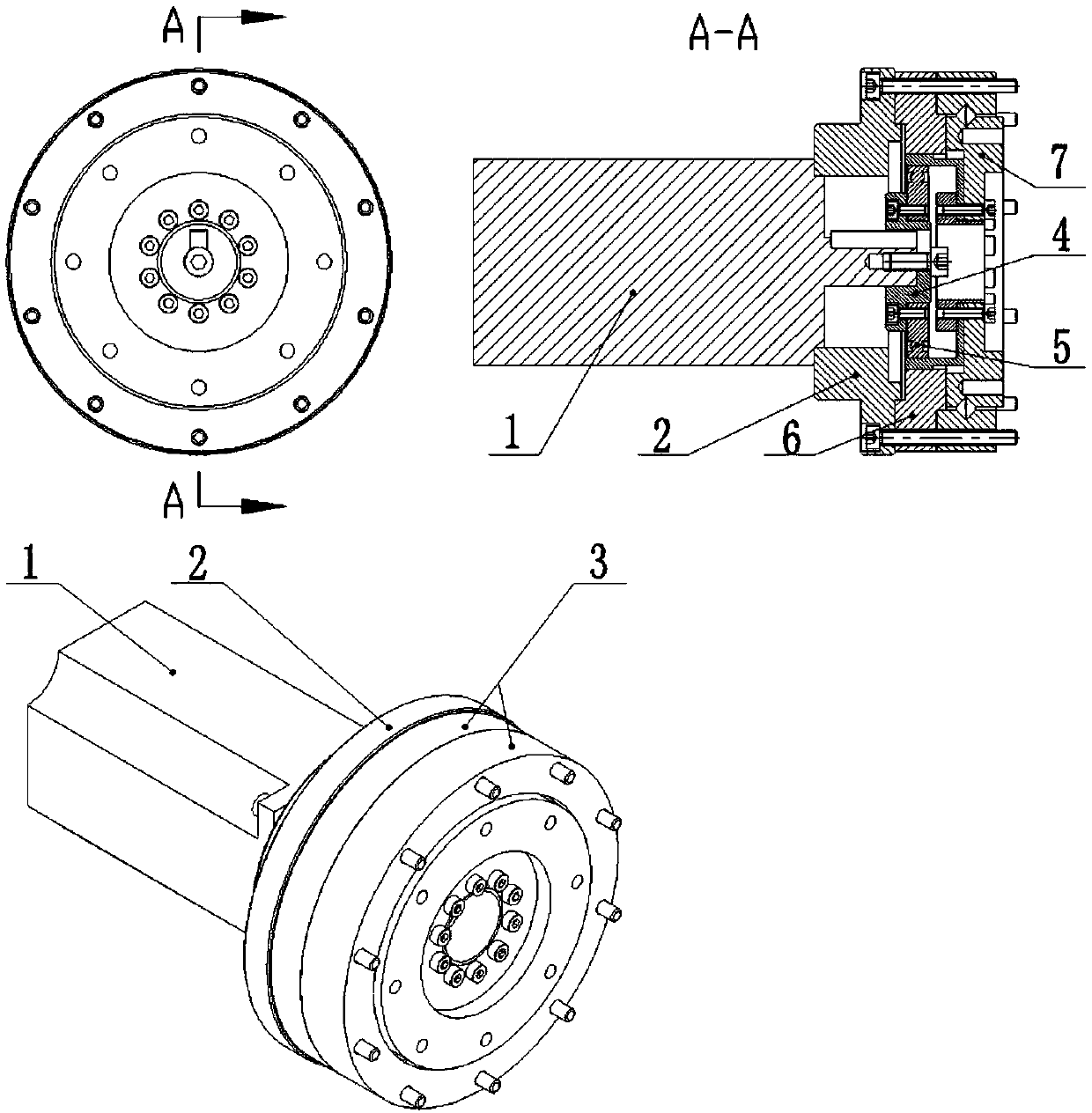
[0027] Specific implementation mode one: refer to figure 1 , the structure of the main motor module of the joint includes a main motor 1 , a main motor support 2 , a reducer 3 , and a main motor shaft sleeve 4 . The reducer 3 is a harmonic reducer with an ultra-flat hollow structure, small volume and large carrying capacity, which meets the requirements of actual operation. The shell of the main motor 1 is fixed on the main motor support 2, the output shaft of the main motor 1 is connected to the wave generator 5 of the harmonic reducer 3 through the main motor bushing 4, and the rigid wheel 6 of the harmonic reducer 3 is connected to the main motor The motor support 2 is fixed together by screws, and the flex spline of the harmonic reducer 3 is connected with the output disc 7 . The output shaft of the main motor 1 and the main motor shaft sleeve 4 are positioned circumferentially and axially through common flat keys and screws. This direct connection reduces the overall len...

specific Embodiment approach 2

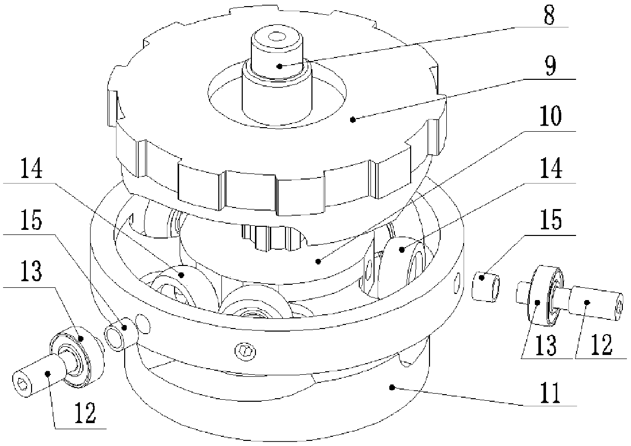
[0029] Specific implementation mode two: combination figure 2 To illustrate, the middle cam roller module is a core module of a variable stiffness joint of a flexible robot, including a spline shaft 8, an upper cam disc 9, a middle disc 10, and a lower cam disc 11. The middle disc 10 has openings in the circumferential direction Six equal-diameter threaded holes, the spherical roller sleeve 14 is equipped with small deep groove ball bearings 13 to form a roller assembly, and the bolt shaft 12 fixes the six roller assemblies to the middle disc 10, and the sleeve I15 is used for radial position.

[0030] The middle disk 10 is connected with the spline shaft 8 through a spline, and the rotation of the spline shaft 8 drives the rotation of the middle disk 10, but the middle disk 10 can move along the axis of the spline shaft 8 due to the axial force. To slide, the spline acts as a guide. The upper cam disc 9 and the lower cam disc 11 are designed with the same curved surface sh...

specific Embodiment approach 3

[0032] Specific implementation mode three: combination image 3 Explain the relationship between the torque and stiffness of the variable stiffness joint and the passive rotation angle, image 3 It is the motion force analysis diagram of the intermediate cam roller module of the variable stiffness joint, which is drawn along the cam circumferential direction. The roller slides along the cam surface, the cam surface is generated by the curve, and the curve Γ is Y=f(θ) in the coordinate system θY-O, which can be further obtained:

[0033] Y B =f(θ B ), Y 3 =Y B +rcos(α B )

[0034] Y D =f(θ D ), Y 4 =Y D +rcos(α D )

[0035]

[0036] Ascent distance: Δy 1 =Y 3 -Y 1 , falling distance: Δy 2 =Y 4 -Y 2

[0037] The total compression of the spring: Δy=Δy 1 +Δy 2

[0038] Spring Force: F a = K spring *Δy

[0039] Upper cam disc torque: T 上凸轮盘 =F τ *R=F a Rtan(α D )

[0040] Lower cam disc torque: T 下凸轮盘 =F τ *R=F a Rtan(α B )

[0041] Joint o...


PUM


Abstract

The invention discloses a flexible robot variable stiffness joint, comprising a main motor module, an intermediate cam roller module, a stiffness adjusting module and a measuring system. An output flange II in the main motor module is fixedly connected with a spline shaft in the intermediate cam roller module, and torque of the main motor module is transmitted to the intermediate cam roller module. A cam roller module includes an upper cam disk, the upper cam disk can slide axially and roll circumferentially on the spline shaft; a mold spring is arranged between the upper cam disk and the flange in the main motor module; the upper cam disk compresses the mold spring to change the torque of the upper cam disk; The lower cam disk is fixedly connected to the output flange I in the stiffness adjustment module.

Description

technical field [0001] The invention relates to a variable stiffness joint of a flexible robot, in particular to a robot joint with disc-shaped cams, rollers and springs as core components to realize variable stiffness, which is suitable for shoulder joints and elbow joints of bionic robots and belongs to the field of robots. Background technique [0002] In the field of traditional industrial robots, robots are heavy, have a fixed working environment, have low flexibility and consume a lot of energy. In order to meet the requirements of manufacturing precision, it is often required that the rigidity of the driver (robot joint) should be as high as possible, and the response speed should be as fast as possible. However, with the continuous expansion of robot application fields, robots have also been liberated from traditional industrial fields and entered other non-industrial fields, such as services, medical care, entertainment, etc. In these fields, especially when the wo...

Claims


Application Information

Patent Timeline
Patent Type & Authority Applications(China)
IPC IPC(8): B25J17/02B25J19/06
CPCB25J17/0258B25J19/068
Inventor 易科胜任武于斌
Owner BEIJING PULIMEN ELECTRO MECHANICAL HIGH TECHN CO
Why Eureka
Try Eureka