Detecting method, device and equipment for temperature of power module of converter and medium

A technology of a power module and a detection method, applied in the field of converters, can solve the problems of low detection accuracy and inapplicability, and achieve the effects of accurate calculation results, strong practicability and wide application range

Active Publication Date: 2018-11-27
BEIJING GOLDWIND SCI & CREATION WINDPOWER EQUIP CO LTD
View PDF6 Cites 15 Cited by
  • Summary
  • Abstract
  • Description
  • Claims
  • Application Information

AI Technical Summary

Problems solved by technology

[0008] In view of the shortcomings of the existing methods, this application proposes a method, device, equipment and medium for detecting the temperature of the power mod

Method used


Image

  • Detecting method, device and equipment for temperature of power module of converter and medium
  • Detecting method, device and equipment for temperature of power module of converter and medium
  • Detecting method, device and equipment for temperature of power module of converter and medium

Examples


Embodiment 1

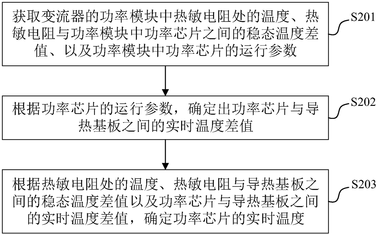
[0049]Embodiment 1 of the present application provides a method for detecting the temperature of a power module of a converter. The schematic flow chart of the detection method is shown in figure 2 shown, including:

[0050] S201. Obtain the temperature at the thermistor in the power module of the converter, the steady-state temperature difference between the thermistor and the power chip in the power module, and the operating parameters of the power chip in the power module.

[0051] Optionally, the operating parameters of the power chip include: average temperature of the power chip, output current, switching times, turn-on duty cycle, and thermal impedance parameters between the power chip and the heat-conducting substrate. The thermistor may be an NTC (Negative Temperature Coefficient, negative temperature coefficient) resistor, so as to reduce temperature fluctuations and improve response speed to temperature changes.

[0052] S202. Determine the real-time temperature d...

Embodiment 2

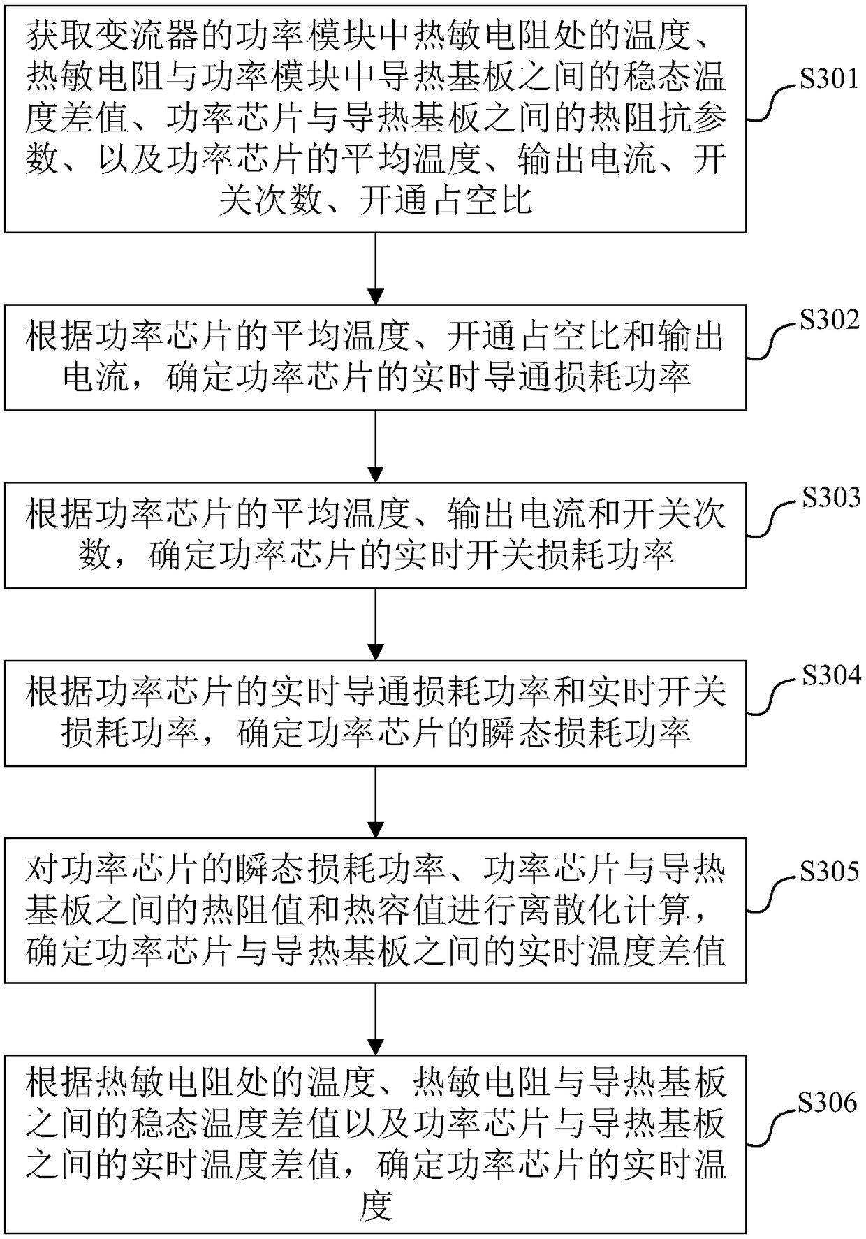
[0068] On the basis of Embodiment 1, another possible implementation provided by Embodiment 2 of this application, such as image 3 As shown, the method includes:

[0069] S301. Obtain the temperature at the thermistor in the power module of the converter, the steady-state temperature difference between the thermistor and the heat conduction substrate in the power module, the thermal impedance parameter between the power chip and the heat conduction substrate, and the power chip The average temperature, output current, switching times, and on-duty cycle of the

[0070] Optionally, the temperature at the thermistor can be detected and determined in advance, and the thermistor can be an NTC resistor, so as to reduce temperature fluctuations and increase the response speed to temperature changes.

[0071] Optionally, the steady-state temperature difference between the thermistor and the thermally conductive substrate can be predetermined by:

[0072] According to the pre-detect...

Embodiment 3

[0143] On the basis of Embodiment 1 or 2, another possible implementation provided by Embodiment 3 of this application, such as Image 6 As shown, the method includes:

[0144] S601. Obtain the temperature at the thermistor in the power module of the converter, the steady-state temperature difference between the thermistor and the heat conduction substrate in the power module, and the operating parameters of the power chip in the power module.

[0145] For the range covered by the operating parameters and the type of the thermistor, reference may be made to the relevant content of Embodiment 1, and details are not repeated here.

[0146] Optionally, for the calculation principle of the steady-state temperature difference between the thermistor and the heat-conducting substrate, reference may be made to the related content of Embodiment 2, which will not be repeated here.

[0147] S602. Determine the real-time temperature difference between the power chip and the heat conducti...


PUM


Abstract

The embodiment of the application provides a detecting method, device and equipment for the temperature of a power module of converter, and a medium. The detecting method comprises the following steps: acquiring the temperature at a thermistor in the power module of the converter, the steady-state temperature difference between the thermistor and a heat conducting substrate in the power module, and operation parameters of a power chip in the power module; determining the real-time temperature difference between the power chip and the heat conducting substrate according to the operation parameters of the power chip; and determining the real-time temperature of the power chip according to the temperature at the thermistor, the steady-state temperature difference between the thermistor and the heat conducting substrate, and the real-time temperature difference between the power chip and the heat conducting substrate. Through the adoption of the embodiment of the application, the real-timetemperature of the power chip in the power module in the converter can be detected, and the detecting efficiency is improved.

Description

technical field [0001] The present application relates to the technical field of converters, and in particular, the present application relates to a method, device, equipment and medium for detecting the temperature of a power module of a converter. Background technique [0002] When the power module of the converter operates at a low frequency, the temperature of the power chips therein usually fluctuates greatly, which will lead to the occurrence of phenomena such as breakage of the bonding wires inside the power module. Therefore, it is necessary to detect the temperature of the power chip, so as to realize more effective temperature control and over-temperature protection of the power chip, and realize the estimation of the service life of the power chip. [0003] At present, for most converters, the temperature of the power chip is usually detected through several schemes: [0004] 1) The temperature of the power chip is estimated by detecting the resistance value of t...

Claims


Application Information

Patent Timeline
IPC IPC(8): G01K7/22
Inventor 王猛文丽婷赵新龙
Owner BEIJING GOLDWIND SCI & CREATION WINDPOWER EQUIP CO LTD
Why Eureka
Try Eureka