Power factor measurement circuit

A technology for measuring circuit and power factor, which is applied in the direction of power factor measurement, electric power measurement, electric variable measurement, etc. It can solve the problems of large amount of calculation, high programming requirements, frequent zero crossing, etc., and achieve enhanced applicability and high sampling accuracy , the effect of reducing random errors

Active Publication Date: 2018-11-27
山西紫东地博科技有限公司 +1
View PDF9 Cites 1 Cited by
  • Summary
  • Abstract
  • Description
  • Claims
  • Application Information

AI Technical Summary

Problems solved by technology

The disadvantage is that this measurement method is only effective when the current and voltage signals must be sine waves. When the signals are non-sinusoidal or there is interference, the frequency will be inaccurate or frequent zero-crossing will cause great fluctuations in the measurement results. error
[000

Method used


Image

  • Power factor measurement circuit
  • Power factor measurement circuit
  • Power factor measurement circuit

Examples


Embodiment Construction

[0015] In order to make the technical solutions and advantages of the present invention clearer, the technical solutions of the present invention will be clearly and completely described below in conjunction with specific embodiments and accompanying drawings. Obviously, the described embodiments are part of the embodiments of the present invention, and Not all of the embodiments; based on the embodiments of the present invention, all other embodiments obtained by those of ordinary skill in the art without creative efforts fall within the protection scope of the present invention.

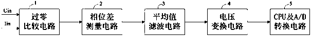
[0016] like figure 1 As shown, the embodiment of the present invention provides a power factor measurement circuit, including a zero-crossing comparison circuit 1, a phase difference measurement circuit 2, an average value filter circuit 3, a voltage conversion circuit 4, a CPU and an A / D conversion terminal acquisition circuit 5 . Wherein, the input terminal of the zero-crossing comparison circui...


PUM


Abstract

The invention belongs to the technical field of circuit measurement and discloses a power factor measurement circuit. The power factor measurement circuit comprises a zero-crossing comparison circuit,a phase difference measurement circuit, an average value filtering circuit, a voltage conversion circuit, a CPU (Central Processing Unit) and an A/D (Analogue/Digital) conversion terminal acquisitioncircuit, wherein the phase difference measurement circuit comprises a multi-way selection switch; after alternating current Iin of a detection loop and alternating voltage Uin of the detection loop pass through the zero-crossing comparison circuit respectively, a first square wave signal and a second square wave signal are output respectively; the first square wave signal is input to a C end od the multi-way selection switch and the second square wave signal is input to a con end od the multi-way selection switch; an H end of the multi-way selection switch is grounded; an output end of the multi-way selection switch is connected with an input end of the average value filtering circuit; the output end of the average value filtering circuit is connected with the input end of the voltage conversion circuit; the output end of the average value filtering circuit is connected with the CPU and the A/D conversion terminal acquisition circuit. The power factor measurement circuit provided by the invention is suitable for measuring power factors of an electric power system, the requirements on an input signal are not high and an applicable range is greatly enlarged.

Description

technical field [0001] The invention relates to the technical field of circuit measurement, in particular to a circuit that can directly obtain the system power factor from the system's alternating current and alternating voltage. Background technique [0002] The current power factor measurement can be obtained by measuring the voltage and current phase difference combined with CPU calculation, and can also be measured by a dedicated power chip combined with CPU. Chinese Patent Publication No. CN1033111A, published on May 24, 1989, the patent name is multi-channel power factor, cycle measurement on-line system, discloses a power factor measurement method, the measured voltage and current signals are adjusted and output through the transformer, Enter their respective zero-crossing comparisons, the time difference of the output pulse frontiers of the two comparators represents the phase difference, and the power factor is obtained through timer measurement and CPU calculation...

Claims


Application Information

Patent Timeline
IPC IPC(8): G01R21/00G01R21/06
CPCG01R21/006G01R21/06
Inventor 高云广赵志诚曹刚张文杰贺玫璐王鑫
Owner 山西紫东地博科技有限公司
Why Eureka
Try Eureka