Long-wave infrared panoramic periscope device

A long-wave infrared and periscope technology, used in telescopes, installations, optics, etc., can solve the problems of large lenses, easy introduction of stray light, and low resolution, and achieve the effect of reducing backlash and stray light.

Pending Publication Date: 2018-11-27
HUAZHONG PHOTOELECTRIC TECH INST (CHINA SHIPBUILDING IND CORP THE NO 717 INST)
View PDF0 Cites 0 Cited by
  • Summary
  • Abstract
  • Description
  • Claims
  • Application Information

AI Technical Summary

Problems solved by technology

Famous domestic universities such as Tsinghua University and Sichuan University have carried out preliminary theoretical and experimental verification research based on the principle of planar cylindrical projection. However, the previous panoramic imaging system (360° field of view) was designed mainly in the visible light band, and there are several different structures. To achieve the required field of view, these structures include rotating cameras, multi-camera stitching, catadioptric systems, and fisheye lenses. The first three solutions increase the complexity and size of the system, and cannot obtain a 360° field of view in real time. Fisheye The lens has been used in several imaging systems with a large field of view, but its spatial resolution varies, and the resolution near the horizontal field of view is the smallest, and when the field of view needs to cover the entire hemisphere, this lens will become very difficult. Big
[0005] Based on the limitation of volume and speed, the panoramic ring lens can be considered to realize the long-wave infrared panoramic periscope application, but the panoramic ring has a large field of view, and it is easy to introduce stray light, and the panoramic ring lens needs to be completed on one lens. Therefore, the main difficulties of the long-wave infrared panoramic periscope include: stray light suppression, panoramic ring lens processing, non-uniformity correction

Method used


Image

  • Long-wave infrared panoramic periscope device
  • Long-wave infrared panoramic periscope device
  • Long-wave infrared panoramic periscope device

Examples


Embodiment Construction

[0025] The present invention will be further described in conjunction with the accompanying drawings and embodiments.

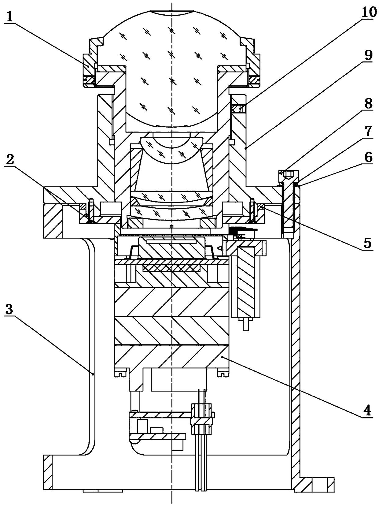
[0026] Such as Figure 1 to Figure 4 As shown, a long-wave infrared panoramic periscope device includes an adapter lens barrel 9 and a device bracket 3 docked up and down, a panoramic annular imaging lens 1 assembled in the adapter lens barrel 9, located in the device bracket 3 and connected to the adapter The infrared detector assembly 4 connected to the lens barrel 9, the panoramic ring imaging lens 1 cooperates with the internal thread of the adapter lens barrel 9, and the axial position is limited by the radial set screw 10, and the adapter lens barrel 9 passes through the circumferential uniform On the flat washer 6 of cloth, spring washer 7 and hexagon socket head cap screw 8 mounting device supports 3.

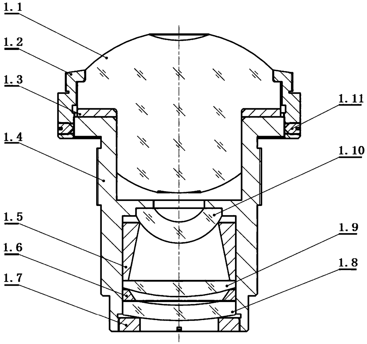
[0027] Such as figure 2 As shown, in this embodiment, the panoramic annular zone imaging lens 1 includes a panoramic annular zone lens 1.1, a front...


PUM


Abstract

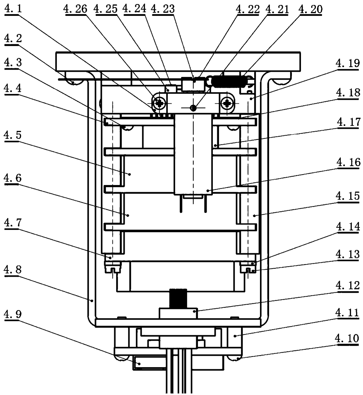
The invention relates to a long-wave infrared panoramic periscope device. The long-wave infrared panoramic periscope device comprises an adapting lens cone butted up and down, a device support frame,a panoramic annular band imaging lens assembled in the adapting lens cone and an infrared detector component located in the device support frame and connected with the adapting lens cone, wherein thepanoramic annular band imaging lens comprises a main lens cone assembled in the adapting lens cone and also comprises a panoramic annular band lens, a front image transferring lens, a middle image transferring lens and a rear image transferring lens which are successively mounted along a center hole of the main lens cone; the thickness of the center of the panoramic annular band lens is close to the diameter of the panoramic annular band lens; the infrared detector component comprises an infrared detector directly facing the rear image transferring lens, a correction baffle, a correction motorused for driving the correction baffle to swing in a small angle to control shielding of the infrared detector and a tension spring with a telescopic end connected with the correction baffle. The device is concentrated in a small-volume space, is capable of achieving inhibition and non-uniform correction of stray light of the panoramic annular band imaging lens and achieving stare long-wave infrared imaging of long-wave infrared band instantaneous peripheral 360-degree target monitoring.

Description

technical field [0001] The invention belongs to the technical field of long-wave infrared sensors, and in particular relates to a long-wave infrared panoramic periscope device. Background technique [0002] In shipborne, submarine, and airborne optoelectronic systems such as tracking, search and navigation, it is increasingly required that the optical system has a larger observation field. At the same time, in special fields, such as periscope systems, airborne systems put forward higher and higher requirements for the volume and weight of optical systems. The biggest design challenge for periscopes should be strict volume requirements. In order to ensure compatibility In the existing photoelectric mast system, the entire sensor system (including optoelectronics) needs to be placed in a small cylinder to detect heat effectively, requiring the optical system to achieve a large field of view within a limited small volume space ( panorama) gaze imaging. [0003] Meeting the m...

Claims


Application Information

Patent Timeline
Patent Type & Authority Applications(China)
IPC IPC(8): G02B23/24G02B7/02G02B13/18
CPCG02B7/026G02B13/18G02B23/2407G02B23/243G02B23/2476
Inventor 姚远郭劼耿安兵王海涛张国伟
Owner HUAZHONG PHOTOELECTRIC TECH INST (CHINA SHIPBUILDING IND CORP THE NO 717 INST)
Why Eureka
Try Eureka