Step up transformer with protection and shock absorption functions

A step-up transformer and functional technology, applied in the field of step-up transformers, can solve the problems of accelerated aging of insulating layers, reduced work efficiency, large losses, etc., and achieve the effects of increasing service life, improving work efficiency, and good performance.

Pending Publication Date: 2018-11-27
张家港鑫峰机电有限公司
View PDF0 Cites 5 Cited by
  • Summary
  • Abstract
  • Description
  • Claims
  • Application Information

AI Technical Summary

Problems solved by technology

The number of the transformers is generally more than three, so it is easy to generate large noise and vibration during operation; therefore, the building adjacent to the transformer room can sense noise and vibration below the fifth floor, so that the existing transformer device affects The daily normal life of the residents, and it can also affect the structural stability of the house; at the same time, the existing transformer needs to increase the lower voltage to a very large voltage when it is used, and the number of turns of the secondary coil needs to be increased. This way to increase the turns ratio to increase the voltage will reduce the heat dissipation effect of the transformer, which will easily lead to overheating of the transformer, increase the internal resistance of the transformer, reduce the working efficiency, accelerate the aging of the insulation layer, and shorten the life of the transformer. Installing any cooling device will easily lead to a short circuit of the transformer, or cause a fire. However, the general transformer is not equipped with any fire protection cover, which will spread the fire to the adjacent electrical equipment, resulting in a large fire and other defects, making the fire Larger losses after the occurrence

Method used


Image

  • Step up transformer with protection and shock absorption functions
  • Step up transformer with protection and shock absorption functions
  • Step up transformer with protection and shock absorption functions

Examples


Embodiment 1

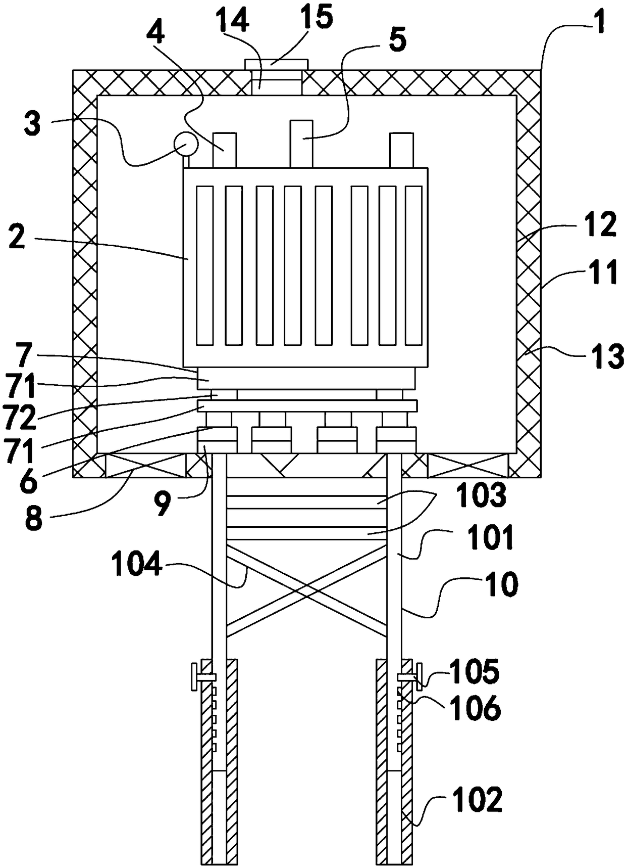
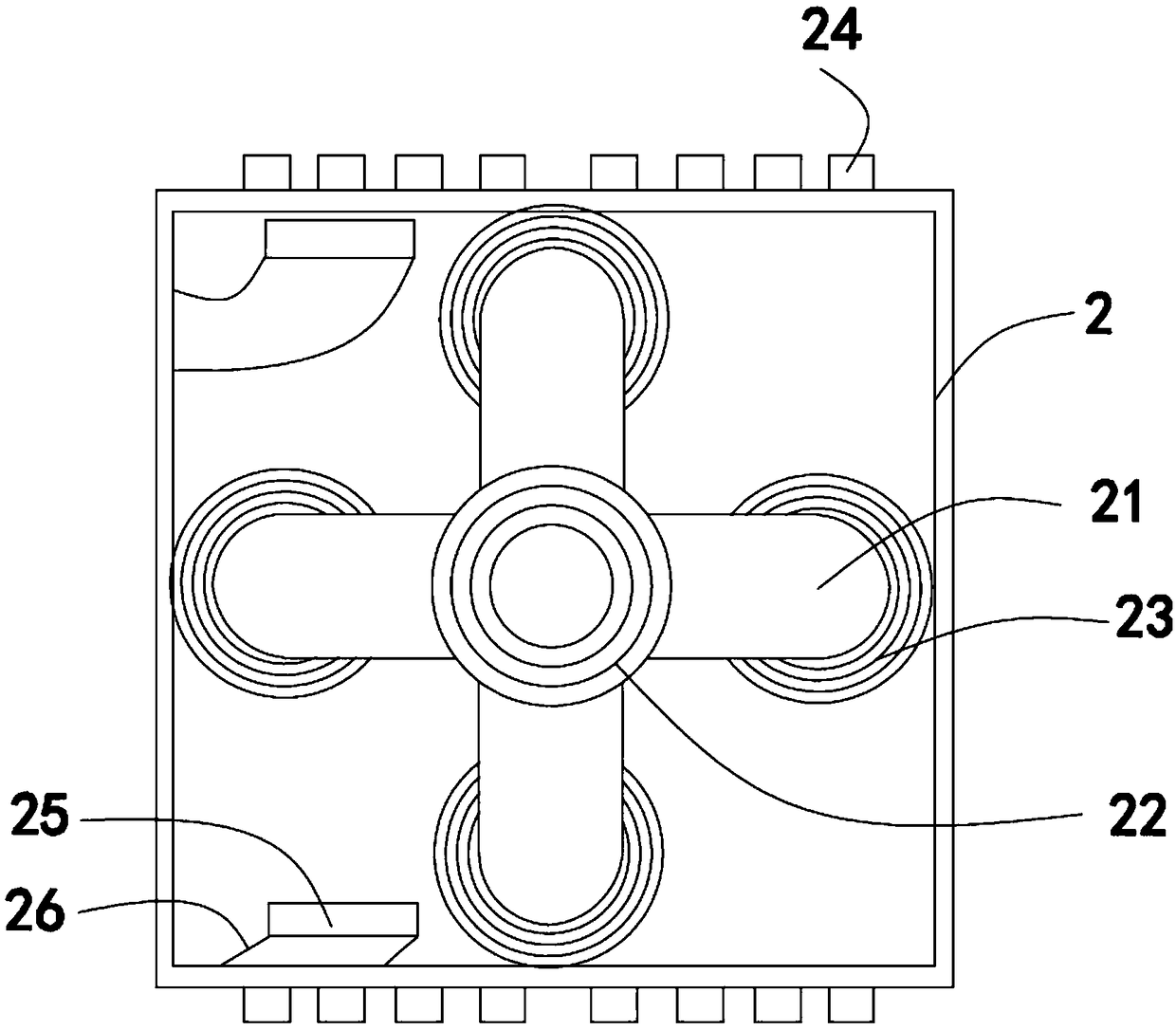
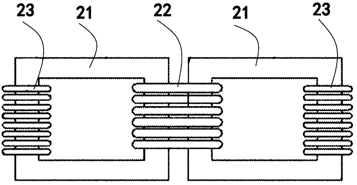
[0027] like Figure 1-Figure 9 As shown, a step-up transformer with protection and shock absorption function described in this embodiment includes a protection box 1 with a sound-absorbing cotton layer 18 inside, a casing 2, a plurality of square-shaped iron cores 21 and adjustable brackets 10. There are at least twelve shock-absorbing devices 6 in a rectangular array on the bottom surface of the inner cavity of the protective box 1, and the top of the shock-absorbing device 6 is fixed with a shock-absorbing plate group 7, and the top surface of the shock-absorbing plate group 7 is fixed to the shell 2, and the shell The top of the housing 2 is provided with a high-voltage insulating sleeve 5, a low-voltage insulating sleeve 4, and an oil conservator 3. A radiator 25 is provided inside the housing 2, and multiple sets of cooling pipes 26 communicating with the radiator 25 are provided on the outer surface of the housing 2. , the circular array of four square iron cores 23 is f...


PUM

PropertyMeasurementUnit
thicknessaaaaaaaaaa

Abstract

The invention discloses a step up transformer with protection and shock absorption functions. Shock absorbers are arranged at the bottom face of an inner cavity of a protection box in a rectangular array, the tops of the shock absorbers are fixedly provided with a shock absorber plate set, a shell is internally provided with a radiator, the outer surface of the shell is provided with a plurality of sets of heat dissipation pipelines communicated with the radiator, square iron cores are fixed on the shock absorber plate set in a circular array, the vertical part of the outer side of each squareiron core is wound with a primary coil, the vertical parts of the inner sides of all the square iron cores are adjacent to one other and wound together through secondary coils; a front end revolvingdoor of the protection box is locked with the side edge of an opening through an anti-theft lock, a top end fixing rod of an adjustable bracket penetrates through the bottom of the protection box andthe bottom of the shell in sequence and is fixedly connected with the shock absorbers, and the bottom of the protection box is provided with a centrifugal exhaust fan. The step up transformer with theprotection and shock absorption functions has the advantages that the structure effectively eliminates the pollution caused by the vibration and noise of the transformer on the normal life of residents, and the use performance of the transformer is better; the loss degree of fire hazards is minimized; the service life of the transformer is prolonged.

Description

technical field [0001] The invention relates to the technical field of transformers, in particular to a step-up transformer with the function of protection and shock absorption. Background technique [0002] A transformer is a common electrical device that can be used to alternately transform a value of a certain value into a voltage of the same frequency with another value of the same frequency; a step-up transformer is used to transform an alternating voltage of a low value into another voltage of the same frequency. A transformer for higher numerical alternating voltages. [0003] At present, due to the planning and supporting requirements of the community, it has become a trend for transformers to enter the building. The number of the transformers is generally more than three, so that it is easy to generate large noise and vibration during operation; therefore, the building adjacent to the transformer room can sense noise and vibration below the fifth floor, so that the...

Claims


Application Information

Patent Timeline
Patent Type & Authority Applications(China)
IPC IPC(8): H01F27/02H01F27/06H01F27/08H01F27/33H01F27/24H01F27/26H01F27/28F16F15/04F16F15/08E05B45/06
CPCH01F27/02E05B45/06F16F15/04F16F15/08H01F27/06H01F27/08H01F27/085H01F27/24H01F27/266H01F27/28H01F27/33
Inventor 吴早荣
Owner 张家港鑫峰机电有限公司
Why Eureka
Try Eureka