A photocatalytic and biological bed compound vocs purification equipment

A kind of purification equipment and photocatalysis technology, which is applied in the direction of chemical instruments and methods, separation methods, and dispersed particle separation, etc., can solve the problems of low purification efficiency, no consideration of changes in gas volume, and unsuitable VOCs gas purification, etc., to achieve improved The effect of purification rate, efficiency improvement and area increase

Active Publication Date: 2021-06-29
东营睿港投资服务有限责任公司
View PDF13 Cites 0 Cited by
  • Summary
  • Abstract
  • Description
  • Claims
  • Application Information

AI Technical Summary

Problems solved by technology

[0004] In the above patent document 1, the VOCs gas is treated by the method of elution oxidation and biodegradation absorption. This invention can effectively treat the VOCs gas, but the content of VOCs treated per unit time is constant. This invention does not consider how to solve the problem. The problem of the change of the amount of gas passed into the purification equipment per unit time is that when the gas is too much, the purification equipment cannot be purified in time, and there will be the problem of incomplete VOCs purification. This invention needs to be improved, and only biological methods are used. Treating VOCs with stripping oxidation method, the purification efficiency is low, and it is not suitable for a large amount of VOCs gas purification

Method used


Image

  • A photocatalytic and biological bed compound vocs purification equipment
  • A photocatalytic and biological bed compound vocs purification equipment
  • A photocatalytic and biological bed compound vocs purification equipment

Examples


Embodiment Construction

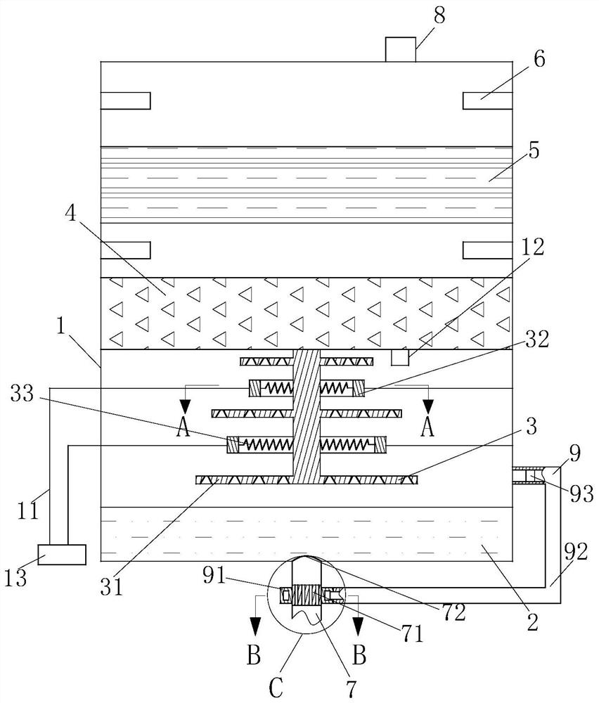
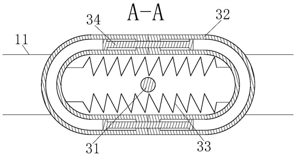
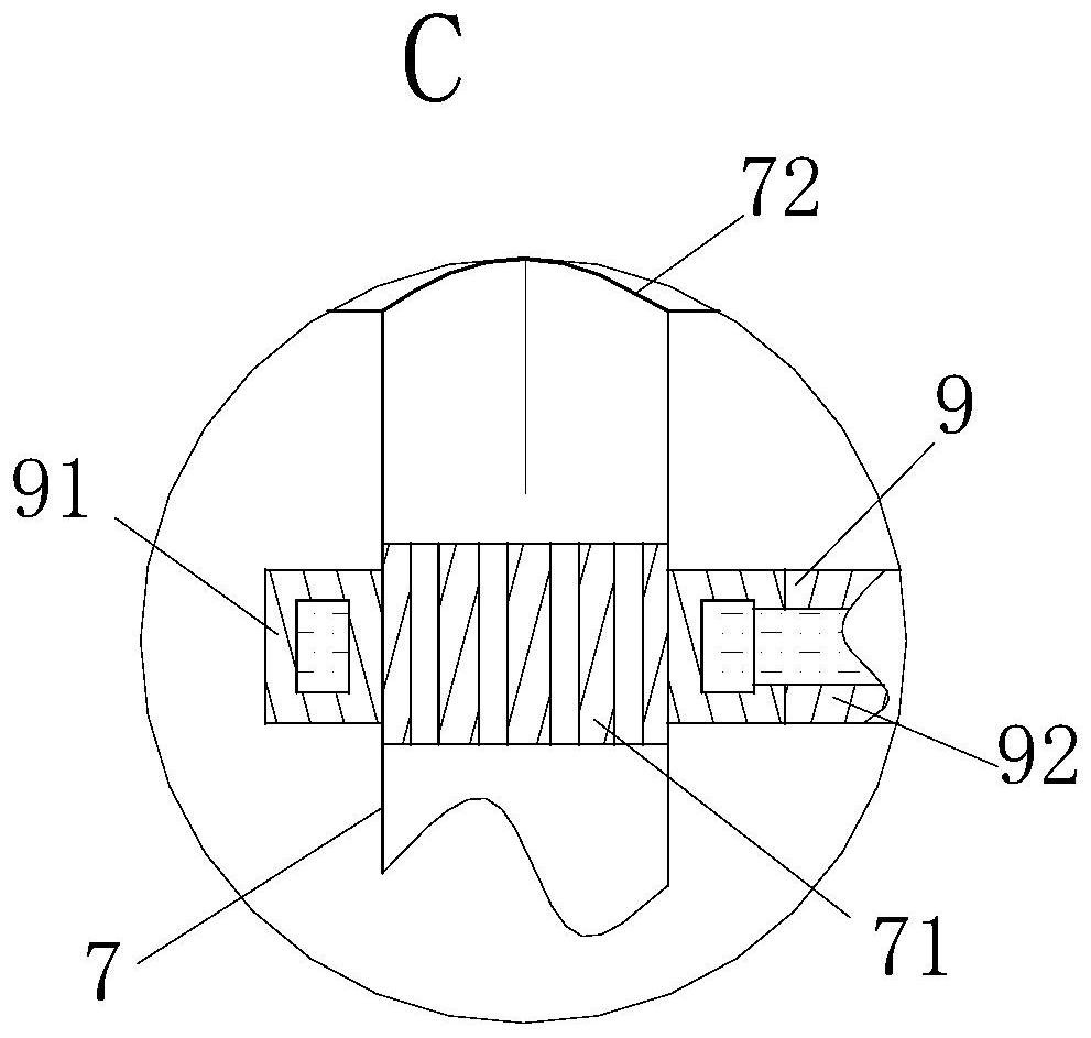
[0022] use Figure 1-Figure 4 The structure of the photocatalytic and biological bed composite VOCs purification equipment according to one embodiment of the present invention is described as follows.

[0023] Such as figure 1As shown, a photocatalytic and biological bed composite VOCs purification device according to the present invention includes a reaction chamber 1, an elution pool 2, a photocatalytic device 3, a biodegradation layer 4, a biofiltration layer 5, a nozzle 6, and a Gas pipeline 7, gas outlet 8 and feedback adjustment device 9; The elution pool 2 is located in the reaction chamber 1, and the elution pool 2 is located at the bottom of the reaction chamber 1, and the elution pool 2 is used to oxidize the VOCs gas, so as to realize the The first layer of VOCs gas treatment; the photocatalytic device 3 is located in the reaction chamber 1, the photocatalytic device 3 is located above the eluting pool 2, and the photocatalytic device 3 is used to catalyze the degr...


PUM


Abstract

The invention belongs to the technical field of exhaust gas purification, specifically a photocatalytic and biological bed composite VOCs purification equipment, including a reaction chamber, an elution pool, a photocatalytic device, a biodegradation layer, a biofiltration layer, a nozzle, and an air intake pipe , gas outlet and feedback adjustment device; the elution pool is located in the reaction chamber, and the elution pool is located at the bottom of the reaction chamber; the photocatalytic device is located in the reaction chamber, and the photocatalytic device is located above the elution pool; The degradation layer is used to biodegrade the VOCs gas; the biofiltration layer is located in the reaction chamber; the nozzles are located in the reaction chamber, and the nozzles are divided into two groups, one group of nozzles is located between the biodegradation layer and the biofiltration layer, and the other group of nozzles is located in the reaction chamber. Above the biological filter layer; the air inlet pipe is located under the elution tank, and the air inlet pipe is used to inject VOCs gas into the elution tank; the gas outlet is located on the upper part of the reaction chamber, and the gas outlet is used to discharge the evolved gas out of the reaction chamber.

Description

technical field [0001] The invention belongs to the technical field of exhaust gas purification, in particular to a photocatalytic and biological bed composite VOCs purification equipment. Background technique [0002] During the production process of the industrial industry, a large amount of waste gas containing VOCs will be generated. If these waste gases are directly discharged into the atmosphere, it will not only cause air pollution, but also lead to waste of materials and increase production costs. In recent years, VOCs emission control work has been carried out in various places. Commonly used VOCs treatment technologies include combustion method, biological method, absorption method, adsorption method, luminescent catalytic method, etc. These methods have certain effects on the treatment of VOCs, but they are also All have their own shortcomings. [0003] Patent Document 1: A compound biological bed purification equipment for VOCs, application number: 2016204411534...

Claims


Application Information

Patent Timeline
Patent Type & Authority Patents(China)
IPC IPC(8): B01D53/75B01D53/44B01D53/84B01D53/88
CPCB01D53/007B01D53/44B01D53/75B01D53/84B01D53/8687B01D53/885B01D2257/708Y02A50/20
Inventor 王鹏
Owner 东营睿港投资服务有限责任公司
Why Eureka
Try Eureka