An ozone catalytic decomposition device

A technology of ozone catalysis and catalytic devices, applied in separation methods, dispersed particle separation, chemical instruments and methods, etc., can solve the problems of easy heating and combustion of activated carbon method, high processing cost, etc., achieve high energy utilization rate, avoid deactivation, The effect of solving long-term utilization problems

Active Publication Date: 2020-11-24
四川蓝主角科技有限公司
View PDF8 Cites 0 Cited by
  • Summary
  • Abstract
  • Description
  • Claims
  • Application Information

AI Technical Summary

Problems solved by technology

For example: the activated carbon method has the problem of easy heating and combustion; the temperature required in the thermal decomposition method is 350°C, and the processing cost is relatively high; the catalytic decomposition method among the above-mentioned methods is currently the most ideal method for controlling the ozone concentration

Method used


Image

  • An ozone catalytic decomposition device
  • An ozone catalytic decomposition device
  • An ozone catalytic decomposition device

Examples


Embodiment 1

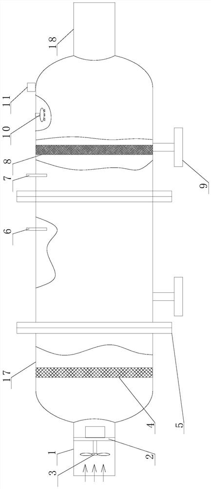
[0045] Such as Figure 1 to Figure 3 As shown, the present embodiment provides a catalytic ozone decomposition device, including a treatment tank 17, an air inlet 1 arranged on the treatment tank 17, an air outlet 18 arranged on the treatment tank 17, located in the treatment tank 17 and interposed In the ozone treatment part between the air inlet 1 and the gas outlet 18, the treatment tank 17 includes a middle section and two head sections, the middle section is cylindrical, and each end of the middle section is connected by a connection method. Lan 5 is fixed with a head section, the air inlet 1 is installed on one of the head sections, and the air outlet 18 is installed on the other head section;

[0046] Described ozone treatment part comprises the catalytic device 8 that is loaded with ozone treatment catalyst, the light source 10 that is contained in the processing tank 17, and light source 10 is arranged near catalytic device 8; 4, and the drying device 4 is located be...

Embodiment 2

[0055] Such as Figure 1 to Figure 3 Shown, this embodiment is further limited on the basis of embodiment 1:.

[0056] As a complete set of equipment design, it also includes a desiccant loaded on the drying device 4, and the desiccant is anhydrous calcium chloride. This desiccant can be used at an ambient temperature of -5°C to 90°C and can be regenerated at the same time.

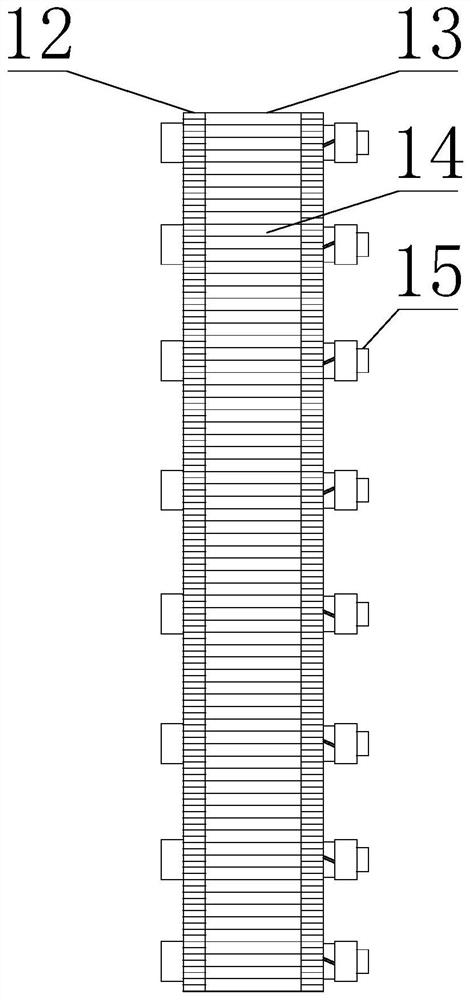
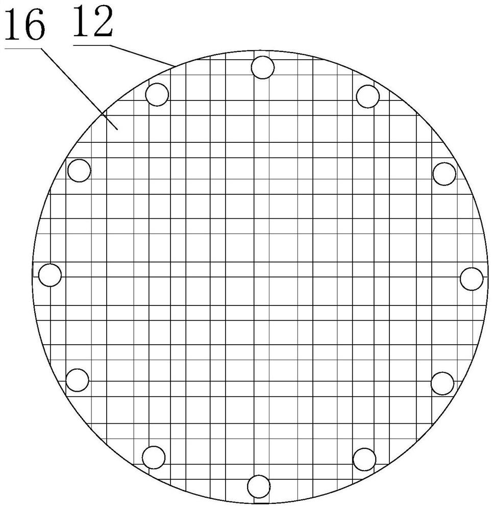
[0057] As a specific implementation of the drying device 4 and the catalytic device 8, the drying device 4 and the catalytic device 8 all include a carrier plate 13 and two end plates 12 for loading the carrier, and the carrier plate 13 is provided with A plate-shaped structure of a plurality of carrier holes 14, and each carrier hole 14 is a through hole through both sides of the carrier plate 13, the carrier hole 14 is used to accommodate the carrier, and the end plate 12 is a mesh-like structure;

[0058] On the drying device 4 or the catalytic device 8 , an end plate 12 is fixed on each side of the ...


PUM


Abstract

The present invention discloses an ozone catalytic decomposition device. The ozone catalytic decomposition device comprises a treatment tank, an air inlet arranged on the treatment tank, an air outletarranged on the treatment tank, and an ozone treatment part located in the treatment tank and arranged between the air inlet and air outlet; the treatment tank comprises an intermediate section and two end socket sections; the intermediate section is cylindrical; each end of the intermediate section is fixed with the end socket section via a connection flange; the air inlet is arranged in one ofthe end socket section; the air outlet is arranged in the other end socket section; the ozone treatment part comprises a catalytic device carrying an ozone treatment catalyst and a light source arranged in the treatment tank; the light source is arranged close to the catalytic device; the ozone treatment part also comprises a drying device arranged in the treatment tank and carrying a desiccant; and besides, the drying device is located between the air inlet and catalytic device. The decomposition device is simple in structure, high in catalytic efficiency and at the same time convenient in maintenance, and can improve utilization rate of consumables.

Description

technical field [0001] The invention relates to the field of ozone decomposition, in particular to an ozone catalytic decomposition device. Background technique [0002] Air pollutants enter the atmosphere (input) from man-made or natural sources, participate in the circulation process of the atmosphere, and after a certain residence time, are removed from the atmosphere (output) through chemical reactions, biological activities and physical deposition in the atmosphere. If the output rate is less than the input rate, it will be relatively concentrated in the atmosphere, resulting in an increase in the concentration of a certain substance in the atmosphere. When the concentration rises to a certain level, it will directly or indirectly cause acute and chronic harm to people, organisms or materials, and the atmosphere will be polluted. Ozone pollution is a type of pollution that is easy to ignore in air pollution but seriously affects people's health, and has received more a...

Claims


Application Information

Patent Timeline
Patent Type & Authority Patents(China)
IPC IPC(8): B01D53/86B01D53/66B01D53/26
CPCB01D53/26B01D53/343B01D53/8675Y02A50/20
Inventor 刘桢李化兰勇王早军彭文茂
Owner 四川蓝主角科技有限公司
Why Eureka
Try Eureka