Valve rod plane semi-automatic lathe

A semi-automatic and flat technology, applied in the field of lathes, can solve the problems of lengthy valve stem processing process and low valve stem production efficiency, and achieve the effect of shortening processing time, facilitating equipment maintenance and reducing processing flow.

Active Publication Date: 2018-11-30
绍兴上虞华源通用机械有限公司
View PDF7 Cites 13 Cited by
  • Summary
  • Abstract
  • Description
  • Claims
  • Application Information

AI Technical Summary

Problems solved by technology

The processing of the valve stem generally requires several steps such as bar cutting, chamfering, drilling, punching the inner hexagon, turning the thread relief groove, turning the sealing ring installation groove, and turning the external thread to the final shape. If mechanical equipment is used for processing, each step needs to be carried out on a separate device, making the entire processing process of the valve stem lengthy, resulting in low production efficiency of the valve stem

Method used


Image

  • Valve rod plane semi-automatic lathe
  • Valve rod plane semi-automatic lathe
  • Valve rod plane semi-automatic lathe

Examples


Embodiment Construction

[0036] The present invention will be described in further detail below in conjunction with the accompanying drawings.

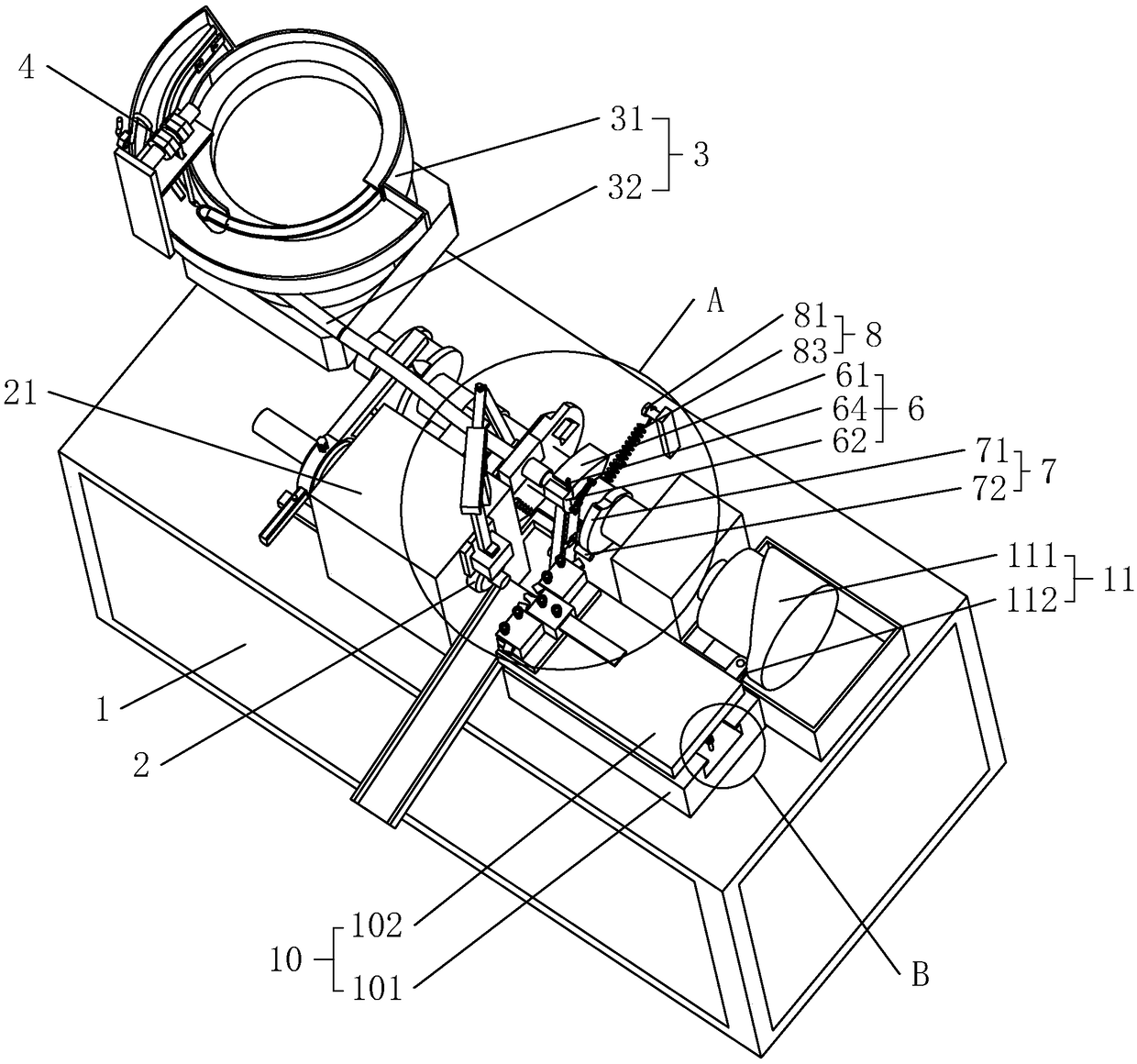
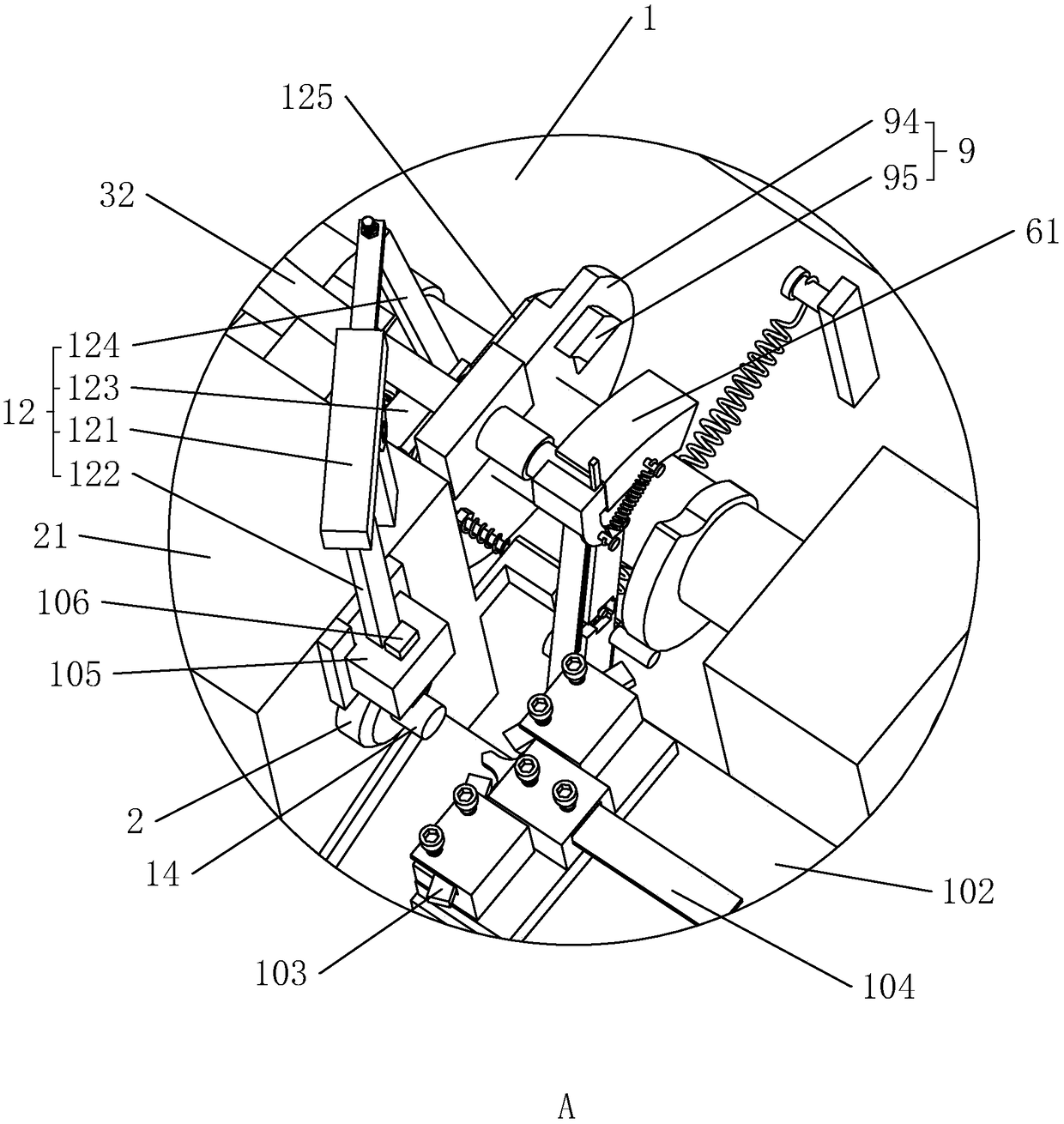
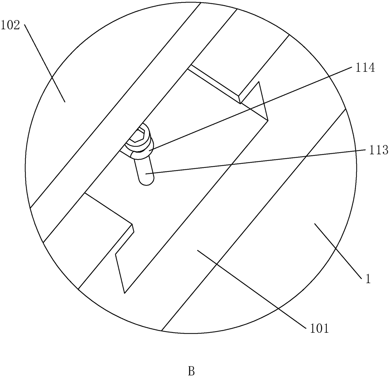
[0037] Such as figure 1 As shown, a valve stem plane semi-automatic lathe includes a frame 1, a main shaft 2, a feeding device 3, a feeding device 6, and a turning device 10. The main shaft 2 is connected to the frame 1 through a mounting seat 21 in rotation; A charging slot for inserting the rod 14 is provided on the installation end, and the main shaft 2 is driven to rotate by a motor.

[0038] The feeding device 3 includes a vibrating plate 31 and a feeding pipe 32. The vibrating plate 31 is fixed on the frame 1. It is a device that uses the principle of vibration to transport parts. It is widely used in the field of mechanical processing and is located in the hopper of the vibrating plate 31. After the parts are vibrated, they rise along the spiral track. During the rising process, after a series of orbital screening or posture changes, the parts can aut...


PUM


Abstract

The invention discloses a valve rod plane semi-automatic lathe. The valve rod plane semi-automatic lathe comprises a frame, and a main shaft rotationally connected to the frame. The valve rod plane semi-automatic lathe further comprises a supply device, a feeding device and a turning device; the turning device comprises a slide rail fixed on the frame, a horizontal cutter base slidingly connectedto the slide rail, a chamfering turning cutter fixed on the horizontal cutter base, a drilling turning cutter, a grooving cutter slidingly connected to a mounting base of a main shaft through a vertical cutter base in a lifting mode, a cutter feeding mechanism arranged on the frame and used for driving the horizontal cutter base and the vertical cutter base to move, and a cutter unloading mechanism; the drilling turning cutter and the rotating axis of the main shaft are positioned on the same straight line; and the chamfering turning cutter is positioned on one side of the drilling turning cutter. In the lathe, rods can be automatically mounted on the main shaft; the chamfering, the drilling and the thread cutter treating groove formation can be performed on the rods at the same time; andafter multiple procedures are integrated on the same equipment, the valve rod machining flow can be reduced, the valve rod machining time is shortened, and the purpose of improving the valve rod production efficiency is improved.

Description

technical field [0001] The invention relates to a lathe, in particular to a valve stem plane semi-automatic lathe. Background technique [0002] Refrigeration units are usually composed of compressors, condensers, expansion valves, evaporators, and control systems. The most important thing in the control system is the control of the refrigerant cycle. Generally includes valve seat, valve core and valve stem and other components. [0003] The valve stem is mainly used for sealing and flow limiting. Generally, the valve stem needs to be processed with external threads, a sealing ring installation groove and an inner hexagonal groove for turning the valve stem after a hexagonal screwdriver is inserted. The processing of the valve stem generally requires several steps such as bar cutting, chamfering, drilling, punching the inner hexagon, turning the thread relief groove, turning the sealing ring installation groove, and turning the external thread to the final shape. If mechan...

Claims


Application Information

Patent Timeline
Patent Type & Authority Applications(China)
IPC IPC(8): B23P23/02B23Q7/00
Inventor 单润民单海峰
Owner 绍兴上虞华源通用机械有限公司
Why Eureka
Try Eureka