
Coal chemical heavy oil sewage treatment technology

A technology for sewage treatment and sewage treatment system, which is applied in water/sewage treatment, biological water/sewage treatment, heating water/sewage treatment, etc. It can solve the problems of high power consumption, high cost and substandard sewage, and save energy. The effect of consumption, tight connection and sufficient settlement

Inactive Publication Date: 2018-11-30
朋仁锋
View PDF0 Cites 2 Cited by
  • Summary
  • Abstract
  • Description
  • Claims
  • Application Information

AI Technical Summary

Problems solved by technology

[0003] At present, the treatment of industrial sewage containing heavy metal ions generally adopts the chemical sedimentation method, but when using the chemical sedimentation method, the chemical reagents cannot be fully mixed with the sewage, resulting in incomplete sedimentation of the heavy metal ions. Electrolysis is also used, but it consumes a lot of electricity. High cost, difficult for users to accept
For the oil in the sewage, especially the heavy oil, the gravity separation method and the adsorption method are mainly used, and the removal rate of the oil substance is only 20-30%, and the treatment effect is not ideal, which brings great difficulties to the subsequent biochemical treatment.
Due to the fragile anti-shock load capacity of the biochemical system itself, the limitation of the traditional denitrification reaction mechanism, and the pressure brought by the pretreatment stage, the treated sewage does not meet the standard; some enterprises adopt the method of increasing the dilution of heavy oil sewage, The concentration of pollutants in the system has dropped significantly, and the effluent has reached the first-level discharge standard. However, a large amount of diluted sewage has increased the processing load of the biochemical station, which has virtually increased the energy consumption and cost of sewage treatment, and caused the company to bear a huge economic burden. principles of cleaner production

Method used


Image

  • Coal chemical heavy oil sewage treatment technology
  • Coal chemical heavy oil sewage treatment technology
  • Coal chemical heavy oil sewage treatment technology

Examples


Embodiment Construction

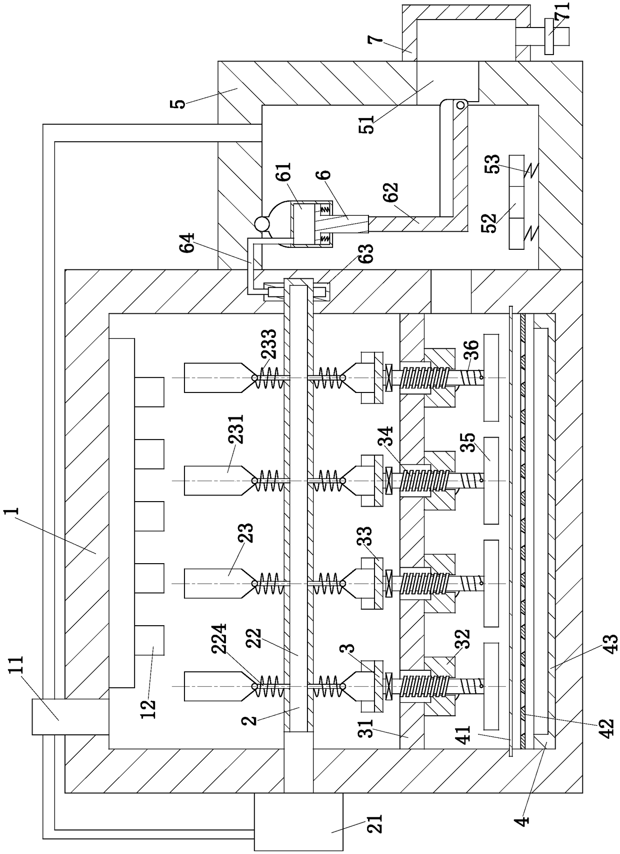
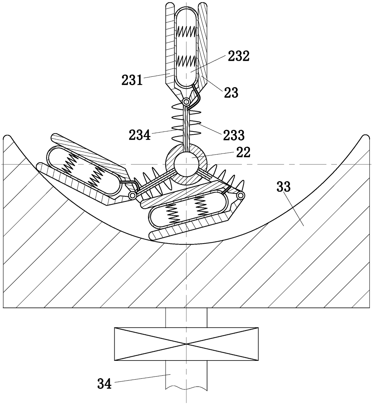
[0027] use Figure 1 to Figure 3 A coal chemical heavy oil sewage treatment process of the present invention is described as follows.

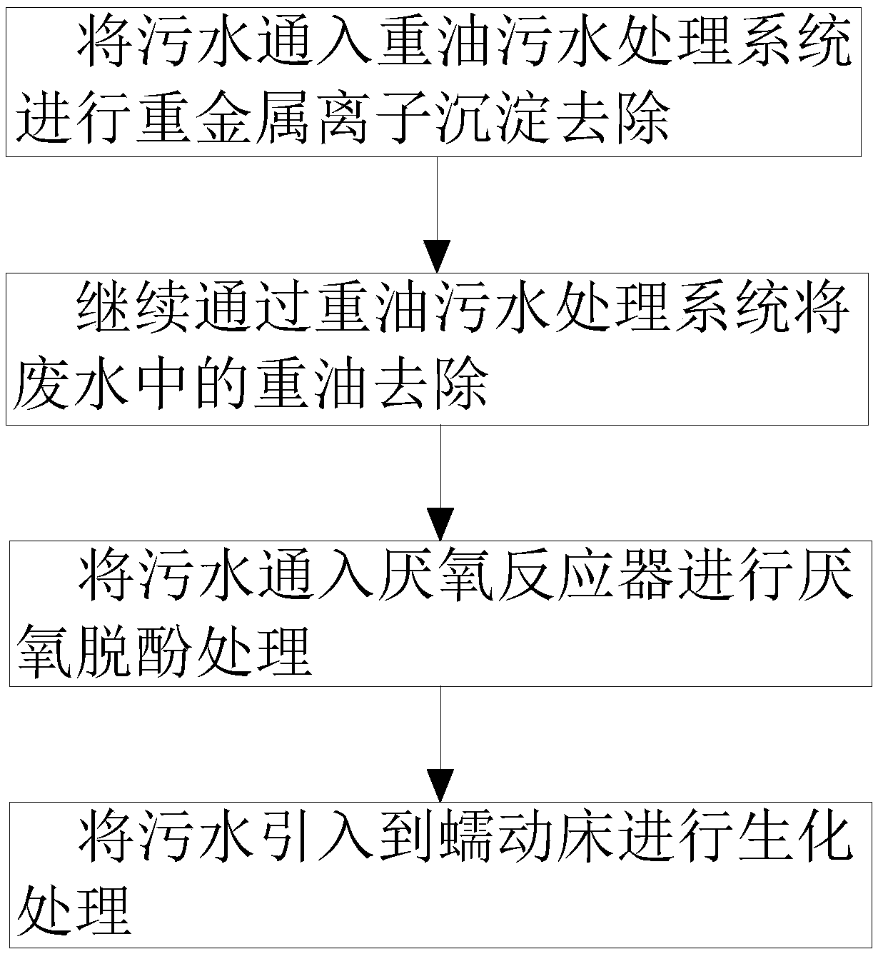
[0028] Such as figure 1 and figure 2 Shown, a kind of coal chemical heavy oil sewage treatment process of the present invention, this process comprises the steps:

[0029] Step 1: Pass the sewage into the heavy oil sewage treatment system for precipitation of heavy metal ions to produce sediment, and remove the sediment;

[0030] Step 2: After the sediment in the sewage is removed in step 1, continue to remove the heavy oil in the sewage through the heavy oil sewage treatment system;

[0031] Step 3: After the heavy oil in the sewage is removed in step 2, the sewage is passed into the anaerobic reactor for anaerobic dephenolization treatment; the anaerobic reactor is a UASB anaerobic reactor, and the hydraulic retention time is 4 to 7 hours. The temperature is 20-35°C; the anaerobic dephenolization treatment is added with anaerobic dephen...


PUM


Abstract

The present invention belongs to the technical field of coal chemical sewage treatment and particularly discloses a coal chemical heavy oil sewage treatment technology. The technology comprises the following steps: sewage passes a heavy oil sewage treatment system for heavy metal ion precipitation to produce a precipitate; the precipitate is removed; the heavy oil sewage treatment system is continuously used to remove heavy oil from the sewage; the sewage passes an anaerobic reactor for an anaerobic dephenolization treatment; the sewage is introduced into a peristaltic bed for a biochemical treatment; and the sewage is discharged after the sewage is treated qualified. The heavy oil sewage treatment system conducts full precipitation of heavy metal ions and removes heavy oil on the upper layer of the sewage; the anaerobic reactor conducts the anaerobic dephenolization treatment of the sewage; and the coal chemical heavy oil sewage treatment technology effectively removes harmful substances of the heavy metal ions, heavy oil, phenols, etc. in the sewage and enables sewage discharge to be up to standard.

Description

technical field [0001] The invention belongs to the technical field of coal chemical industry sewage treatment, and specifically relates to a coal chemical heavy oil sewage treatment process. Background technique [0002] At present, in the coal gasification sewage treatment industry, there are many heavy metal ions, heavy oil and phenols in the sewage after deacidification and deamination. Therefore, it is necessary to settle the heavy metal ions, separate the heavy oil in the sewage, and separate the sewage removal of phenols in. [0003] At present, the treatment of industrial sewage containing heavy metal ions generally adopts the chemical sedimentation method, but when using the chemical sedimentation method, the chemical reagents cannot be fully mixed with the sewage, resulting in incomplete sedimentation of the heavy metal ions. Electrolysis is also used, but it consumes a lot of electricity. The cost is high, and it is difficult for users to accept it. For the oil ...

Claims


Application Information

Patent Timeline
IPC IPC(8): C02F9/14C02F101/20C02F101/34
CPCC02F9/00C02F1/04C02F1/40C02F1/5281C02F3/00C02F3/28C02F3/34C02F2101/20C02F2101/345C02F2303/04
Inventor 朋仁锋
Owner 朋仁锋
Learn More