Two-stage sludge hydrothermal reaction device

A technology of sludge water and heat reaction, applied in the direction of controlling sludge treatment through temperature, can solve the problems of high cost, bulky, complex structure, etc., and achieve the effect of reducing installed power, improving stirring intensity and reducing stirring power.

Inactive Publication Date: 2018-11-30
四川深蓝环保科技有限公司
View PDF4 Cites 2 Cited by
  • Summary
  • Abstract
  • Description
  • Claims
  • Application Information

AI Technical Summary

Problems solved by technology

[0005] However, looking at the hydrothermal process systems adopted by various companies engaged in hydrothermal technology at home and abroad, whether it is a continuous process or a sequential batch process, the hydrothermal reactor integrates "heating", "stirring" and "reaction (retention)". In one, the hydrothermal reactor is used as the main reaction equipment. In order to ensure sufficient reaction temperature, pressure, time, and mixing degree, most of them are bulky, complex in structure, and expensive.

Method used


Image

  • Two-stage sludge hydrothermal reaction device
  • Two-stage sludge hydrothermal reaction device

Examples


Embodiment 1

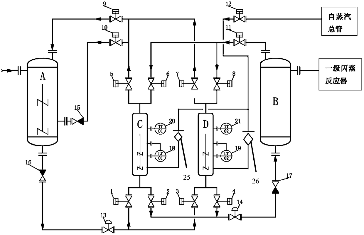
[0027] like figure 1As shown, in a preferred embodiment of the present invention, there are two hydrothermal heating reactors of the two-stage sludge hydrothermal reaction device, and they are arranged in parallel. Of course, those skilled in the art should understand that the There can be 3 or more hydrothermal heating reactors, among which 2 or 3 are the best, and multiple feeders, outlets or other related components can be shared between multiple reactors. Stable continuous use of incoming and outgoing materials and air sources to reduce system fluctuations. Specifically, the device includes: the slurry reactor A arranged last is arranged horizontally with the hydrothermal heating reactor C and the hydrothermal heating reactor D, and the hydrothermal heating reactor C and the hydrothermal heating reactor D are arranged in parallel , the automatic switching is used alternately, so that the discharge of the slurry reactor A and the feed of the hydrothermal retention reactor ...

Embodiment 2

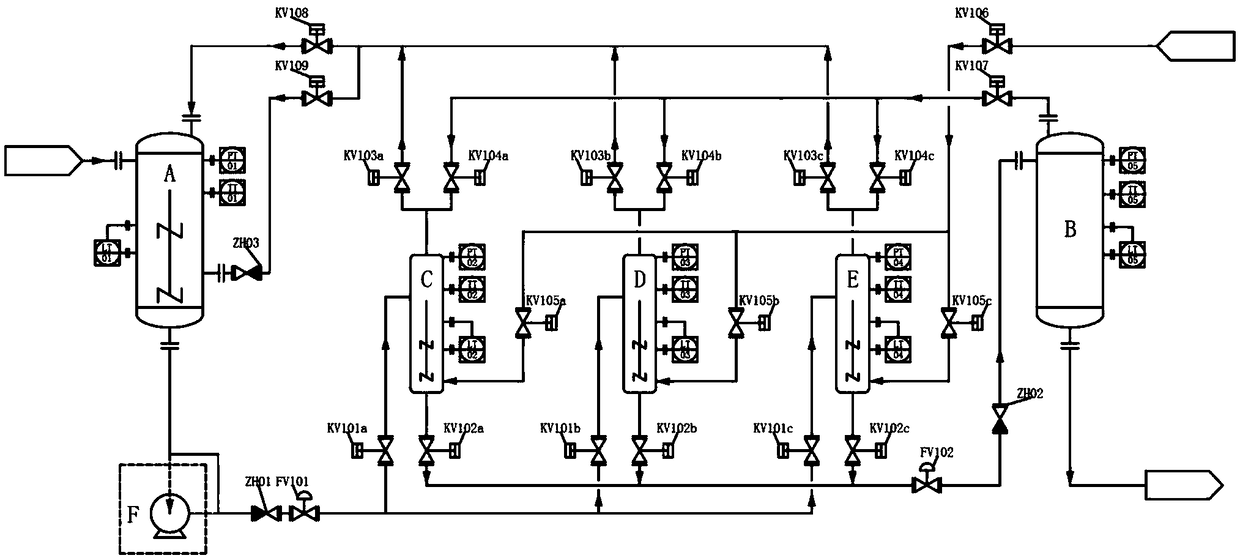
[0048] like figure 2 As shown, in this embodiment, the hydrothermal heating reactor is provided with three (C / D / E), arranged in parallel, the connection relationship between the three heating and conveying, and their connection with the final slurry reactor and The connection relationship between the hydrothermal retention reactors is basically the same as the connection relationship between the two units in Embodiment 1, and will not be repeated here.

[0049] Different from Embodiment 1, in this embodiment, not only temperature and liquid level monitoring, but also pressure monitoring and pressure transmitters are installed for each hydrothermal heating reactor (C / D / E) , in addition, three transmitters of temperature TT, liquid level LT and pressure PT are also set up for the slurry reactor A and the hydrothermal retention reactor B for monitoring, among which, the hydrothermal heating reactor (C / D / E ) to the hydrothermal stagnation reactor B, it is necessary to control th...


PUM


Abstract

The invention discloses a two-stage sludge hydrothermal reaction device. The device comprises: a plurality of slurrying reactors which are serially connected from front to back, a hydrothermal residence reactor and a plurality of flash evaporation reactors which are serially connected from front to back, and the hydrothermal residence reactor is arranged between the backmost slurrying reactor andthe headmost flash evaporation reactor, wherein at least one hydrothermal temperature reactor is also mounted between the hydrothermal residence reactor and the backmost slurrying reactor, every hydrothermal heating reactor is provided with a gas inlet tube, a gas outlet tube, a steam tube, a feed tube and a discharging tube which are connected with the corresponding hydrothermal heating reactor,a plurality of the hydrothermal heating reactors alternately run, and arrangement according to a preset timing sequence makes the discharging of the final-stage slurrying reactor and the feeding of the hydrothermal residence reactor continuously performed. The two-stage sludge hydrothermal reaction device disclosed in the invention simplifies the heating function of the hydrothermal reactor, and realizes good stirring performance, energy saving and high sludge treatment efficiency of the hydrothermal reactor.

Description

technical field [0001] The invention relates to the technical field of solid waste treatment, in particular to a modification treatment technology for municipal or industrial sludge, and in particular to a two-stage sludge hydrothermal reaction device. Background technique [0002] In recent years, the urbanization process has become faster and faster, and the generation and treatment rate of urban domestic sewage are also increasing. Although various methods have been adopted to reduce the output of urban sludge, the total amount is still at an annual rate of 10%. rate increments. Sludge from sewage treatment plants is generally "anaerobic digestion-dosing dehydration" to reach a water content of about 80%, and then transported to sanitary landfills for landfill. 80% of the sludge still has a certain fluidity, which brings inconvenience to the landfill operation, and there is a hidden danger of secondary pollution. As the state strengthens the final disposal management of...

Claims


Application Information

Patent Timeline
Patent Type & Authority Applications(China)
IPC IPC(8): C02F11/18
CPCC02F11/18
Inventor 邓舟夏洲张超荀锐陈科宇金涛李刚
Owner 四川深蓝环保科技有限公司
Why Eureka
Try Eureka