Fuel oil and fuel gas steam boiler

A gas steam and fuel oil technology, applied in steam boilers, steam generation, combustion methods, etc., can solve the problems of poor heat exchange effect, large fuel consumption, short flow of smoke pipes, etc., and achieve improved performance, long service life, and energy saving. The effect of environmentally friendly heat

Inactive Publication Date: 2018-11-30
FOSHAN JIHE TECH CO LTD
View PDF0 Cites 2 Cited by
  • Summary
  • Abstract
  • Description
  • Claims
  • Application Information

AI Technical Summary

Problems solved by technology

Due to the limitation of the structure, the flow of the flue pipe is short, the flue gas flow rate is slow, and the heat exchange effect is poor; at the same time, due to the large water capacity in the furnace, the fuel consumption is large when the boiler is started, and the fuel waste is serious when the heat exchange effect is poor.

Method used


Image

  • Fuel oil and fuel gas steam boiler
  • Fuel oil and fuel gas steam boiler
  • Fuel oil and fuel gas steam boiler

Examples


Embodiment 1

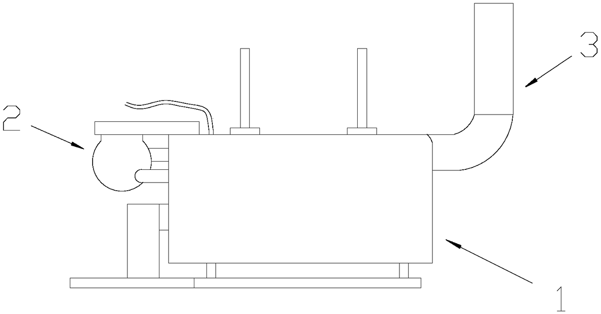
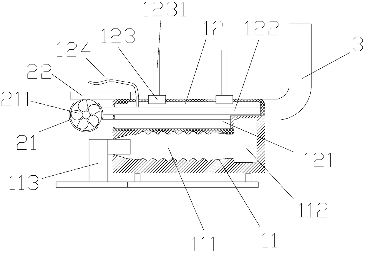
[0030] A fuel gas steam boiler, such as figure 1 As shown, it includes a combustion furnace body 1, a turbocharger blower 2 arranged above the combustion furnace body 1 and communicated with the combustion furnace body 1, and a chimney 3 arranged on the other side of the combustion furnace body 1; Such as figure 2 As shown, the combustion furnace body 1 includes a combustion chamber 11, and a water storage chamber 12 arranged above the combustion chamber 11; The tempering chamber 112, and the burner 113 that is arranged at the other end of the combustion passage 111 and is located outside the combustion chamber 11; the water storage chamber 12 is provided with one end communicating with the tempering chamber 112 and the other end communicating with the turbocharger The first return pipe 121 connected to the compressor 2, and the second return pipe 122 arranged above the first return pipe 121, one end communicated with the turbocharger fan 2, and the other end communicated wi...

Embodiment 2

[0042] A fuel gas steam boiler, such as figure 1 As shown, it includes a combustion furnace body 1, a turbocharger blower 2 arranged above the combustion furnace body 1 and communicated with the combustion furnace body 1, and a chimney 3 arranged on the other side of the combustion furnace body 1; Such as figure 2 As shown, the combustion furnace body 1 includes a combustion chamber 11, and a water storage chamber 12 arranged above the combustion chamber 11; The tempering chamber 112, and the burner 113 that is arranged at the other end of the combustion passage 111 and is located outside the combustion chamber 11; the water storage chamber 12 is provided with one end communicating with the tempering chamber 112 and the other end communicating with the turbocharger The first return pipe 121 connected to the compressor 2, and the second return pipe 122 arranged above the first return pipe 121, one end communicated with the turbocharger fan 2, and the other end communicated wi...

Embodiment 3

[0054] A fuel gas steam boiler, such as figure 1 As shown, it includes a combustion furnace body 1, a turbocharger blower 2 arranged above the combustion furnace body 1 and communicated with the combustion furnace body 1, and a chimney 3 arranged on the other side of the combustion furnace body 1; Such as figure 2 As shown, the combustion furnace body 1 includes a combustion chamber 11, and a water storage chamber 12 arranged above the combustion chamber 11; The tempering chamber 112, and the burner 113 that is arranged at the other end of the combustion passage 111 and is located outside the combustion chamber 11; the water storage chamber 12 is provided with one end communicating with the tempering chamber 112 and the other end communicating with the turbocharger The first return pipe 121 connected to the compressor 2, and the second return pipe 122 arranged above the first return pipe 121, one end communicated with the turbocharger fan 2, and the other end communicated wi...


PUM

PropertyMeasurementUnit
lengthaaaaaaaaaa

Abstract

The invention discloses a fuel oil and fuel gas steam boiler. The fuel oil and fuel gas steam boiler comprises a combustion furnace body, a turbocharging fan above one side of the combustion furnace body and a chimney arranged above the other side of the combustion furnace body; the combustion furnace body comprises a combustion chamber and a water storage chamber, the combustion chamber comprisesa combustion channel, a reversing chamber and a combustor, a first return pipe, a second return pipe arranged above the first return pipe, a steam output valve arranged above the water storage chamber and a water inlet pipe arranged above the water storage chamber are arranged in the water storage chamber, through the combustion chamber composed of the combustion channel and the reversing chamber, oil and gas can be sufficiently combusted, and the effects of energy saving, environment friendliness and heat increasing are achieved; through the first return pipe and the second return pipe, thesmoke gas conveying path can be prolonged, the heat exchange effect is improved, the first return pipe and the second return pipe are rapid in heat conduction, the resource waste caused by direct discharging of heat along with smoke gas can be reduced, and the boiler is suitable for boiler heat recycling.

Description

technical field [0001] The invention relates to a fuel gas steam boiler. Background technique [0002] The boiler is a kind of energy conversion equipment. The energy input into the boiler can be chemical energy, electric energy, etc. After being converted by the boiler, it outputs steam, high-temperature water or organic heat carrier with certain heat energy, which can be used in power stations, ships and locomotives etc., making it play an irreplaceable role both in industry and in life; due to the scarcity of coal energy, traditional coal-fired boilers are now being phased out, and environmental protection bureaus around the world require coal-fired boilers to be converted into clean energy , The emerging natural gas is a clean energy with low cost, high combustion rate and low emission, which can meet environmental protection requirements. [0003] Traditional oil-fired gas-fired steam boilers are mostly vertical, and adopt a two-return structure consisting of a lower f...

Claims


Application Information

Patent Timeline
Patent Type & Authority Applications(China)
IPC IPC(8): F22B31/00F23L17/00C04B33/04C04B33/13C04B33/16C04B33/32C04B33/36
CPCF22B31/00C04B33/04C04B33/13C04B33/16C04B33/32C04B33/36C04B2235/3206C04B2235/3208C04B2235/3218C04B2235/3481C04B2235/422F23L17/005
Inventor 夏放军
Owner FOSHAN JIHE TECH CO LTD
Why Eureka
Try Eureka