Farming robot

A robot and robot body technology, applied in the field of farming robots, can solve the problems of low farmland efficiency, high motor power consumption, and high manufacturing costs, and achieve the effects of improving space utilization, prolonging service life, and low manufacturing costs.

Inactive Publication Date: 2018-12-07
杨程
View PDF9 Cites 0 Cited by
  • Summary
  • Abstract
  • Description
  • Claims
  • Application Information

AI Technical Summary

Problems solved by technology

[0003] The application number is CN201711435131.2, a vibratory plowing device, although it can effectively break up large soil clods and can conveniently adjust the depth of plowing, it solves the problem that many large soil clods often remain after plowing At the same time, it can also solve the problem that the rotating blade is easily broken or damaged when encountering stones and bricks, but its structure is relatively complicated, the power consumption of the motor is large, and the manufacturing cost is high.
[0004] The application number is CN201710591208.9, which is a farmland sowing robot with solar power generation function. Although it can improve the battery life of the robot and can retract and retract the solar panel, it is safer and more convenient. Through the tillage and sowing mechanism , can loosen the land and stir the seeds, which improves the germination rate of the sowing, but the efficiency of the cultivated land is low, and the function of efficient and continuous cultivated land cannot be realized

Method used


Image

  • Farming robot
  • Farming robot
  • Farming robot

Examples


Embodiment Construction

[0027] Below in conjunction with accompanying drawing, technical scheme of the present invention is described in further detail:

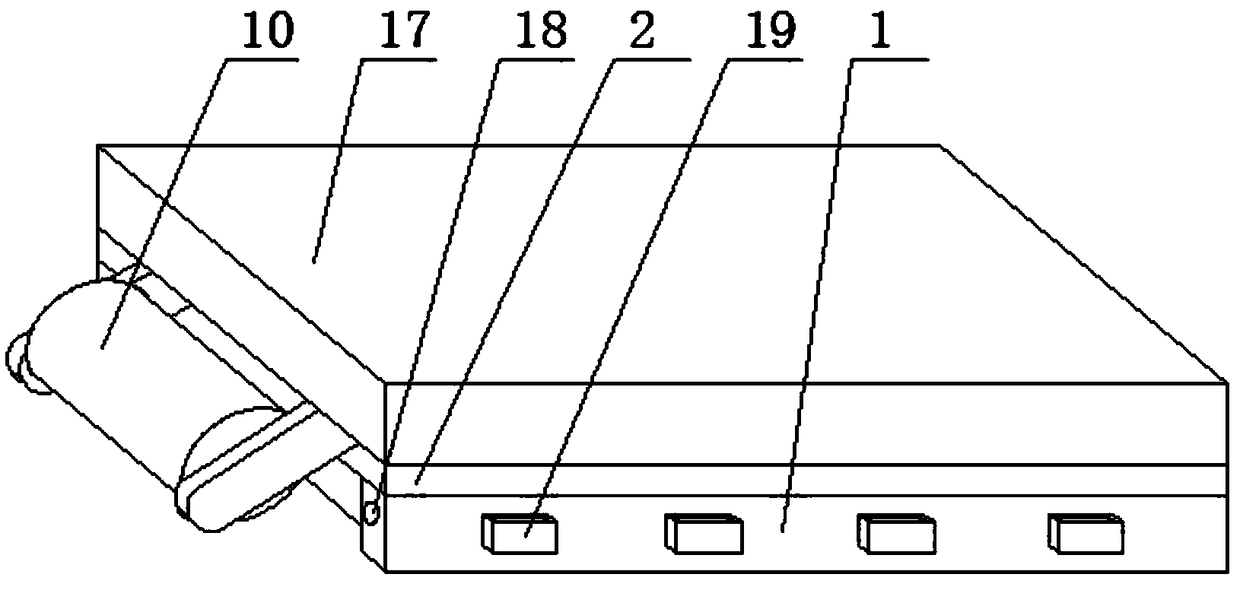
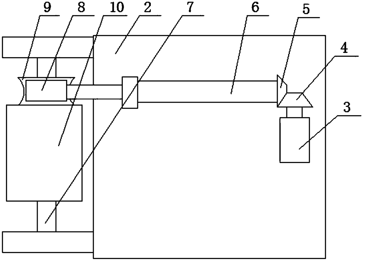
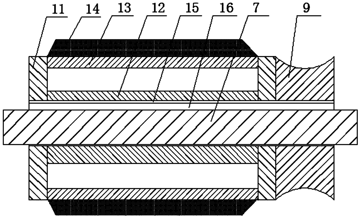
[0028] Such as Figure 1 to Figure 3 As shown, a farming robot includes a robot body 1, a load plate 2, a servo motor 3, a bevel gear I4, a bevel gear II5, a gear shaft 6, a tiller shaft 7, a worm 8, a turbine 9 and a rotary tiller module 10; The bottom end of the carrying plate 2 is fixedly connected to the top of the robot body 1; the bottom end of the servo motor 3 is fixedly connected to the top of the carrying plate 2, and the gear shaft 6 is rotatably connected to the end of the carrying plate 2 through a bearing. The top; the bevel gear I4 is fixedly connected to the shaft of the servo motor 3 through a key, the bevel gear II5 is connected to one end of the gear shaft 6 through a key, and the other end of the gear shaft 6 is connected to the worm 8 through a coupling, The bevel gear I4 is meshed with the bevel gear II5, and the worm gear 9 ...


PUM


Abstract

The invention discloses a farming robot. The robot comprises a robot body, a bearing plate, a servo motor, a bevel gear I, a bevel gear II, a gear shaft, a tilling cutter shaft, a worm, a turbine anda rotary tillage cutter module; the bottom end of the bearing plate is fixedly connected with the top end of the robot body; the bottom end of the servo motor is fixedly connected with the top end ofthe bearing plate, and the gear shaft is rotationally connected to the top end of the bearing plate through a bearing; the bevel gear I is fixedly connected with a shaft of the servo motor through a key, the bevel gear II is connected with one end of the gear shaft through a key, and the other end of the gear shaft is connected with the worm through a coupler; the bevel gear I is meshed with the bevel gear II, and the turbine is meshed with the worm; the turbine is fixedly connected with one end of the rotary tillage cutter module, and the turbine and the rotary tillage cutter module are connected with the tilling cutter shaft through keys together; the two ends of the tilling cutter shaft are rotationally connected to the front end of the bearing plate through bearings. The robot achievesthe functions of low power consumption and continuous and efficient ploughing.

Description

technical field [0001] The invention relates to the field of robots, in particular to a farming robot. Background technique [0002] Farming robots are used in agriculture to replace human labor robots, and the use of robots to sow seeds can improve work efficiency. [0003] The application number is CN201711435131.2, a vibratory plowing device, although it can effectively break up large soil clods and can conveniently adjust the depth of plowing, it solves the problem that many large soil clods often remain after plowing , At the same time, it can also solve the problem that the rotary blade is easily broken or damaged when encountering stones and bricks, but its structure is relatively complicated, the power consumption of the motor is large, and the manufacturing cost is high. [0004] The application number is CN201710591208.9, which is a farmland sowing robot with solar power generation function. Although it can improve the battery life of the robot and can retract and...

Claims


Application Information

Patent Timeline
Patent Type & Authority Applications(China)
IPC IPC(8): A01B33/02A01B33/08A01B33/10A01B33/12A01B33/16
CPCA01B33/021A01B33/08A01B33/082A01B33/103A01B33/12A01B33/16
Inventor 杨程
Owner 杨程
Why Eureka
Try Eureka