Full-automatic vertical type red punching equipment

A fully automatic, red punching technology, used in metal processing equipment, metal extrusion control equipment, sorting and other directions, can solve the problems of equipment requiring special personnel to operate, complex structure, and low control accuracy.

Active Publication Date: 2018-12-07
彪马集团有限公司
View PDF8 Cites 15 Cited by
  • Summary
  • Abstract
  • Description
  • Claims
  • Application Information

AI Technical Summary

Problems solved by technology

[0003] In the patent document with the authorized announcement number CN203438577U, an automatic red punching machine is disclosed. Although the traditional operation method has been changed, the structure described in the document is too complicated, there are too many transmission parts and control parts, and the control accuracy is not high. One piece of equipment needs to be operated by a special person, the labor cost is high, and the maintenance is inconvenient;
[0004] Chinese patent (its application number is: 201721359200.1; its announcement number is: CN207238780 U), discloses a kind of automatic horizontal hot extrusion machine, comprises, comprises base plate and the forming device that is located on the base plate, forming device comprises punch, The die and the left vertical plate and right vertical plate fixedly installed on the bottom plate, one end of the small guide column is fixedly connected with the short horizontal plate, and the middle part of the end of the short horizontal plate adjacent to the long horizontal plate is installed with a push column, and the push column slides Through the long horizontal plate, the long horizontal plate is equipped with a locking block and a locking cylinder corresponding to the push column, and the middle part of the end adjacent to the right vertical plate is installed with a push rod, and the push rod penetrates into the inner part of the die After the molding is completed, the material is ejected; the extruder of this patent is a horizontal structure, which takes up a lot of space, and the production efficiency and safety need to be improved, which is not conducive to the promotion of enterprises

Method used


Image

  • Full-automatic vertical type red punching equipment
  • Full-automatic vertical type red punching equipment
  • Full-automatic vertical type red punching equipment

Examples


Embodiment

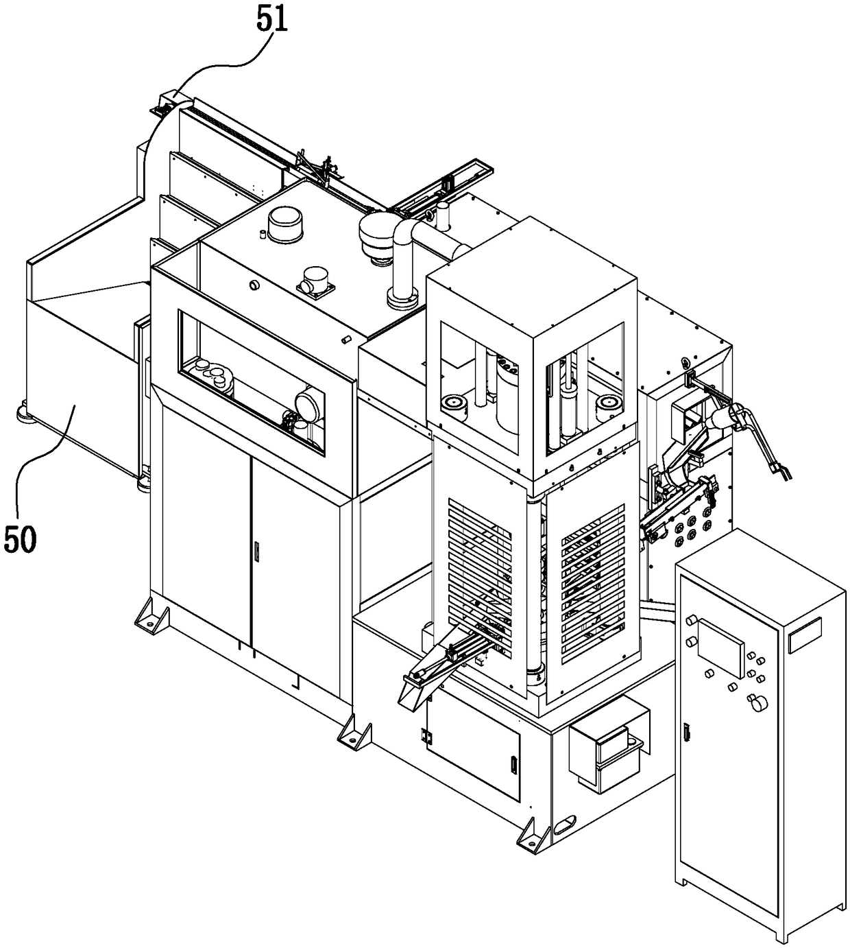
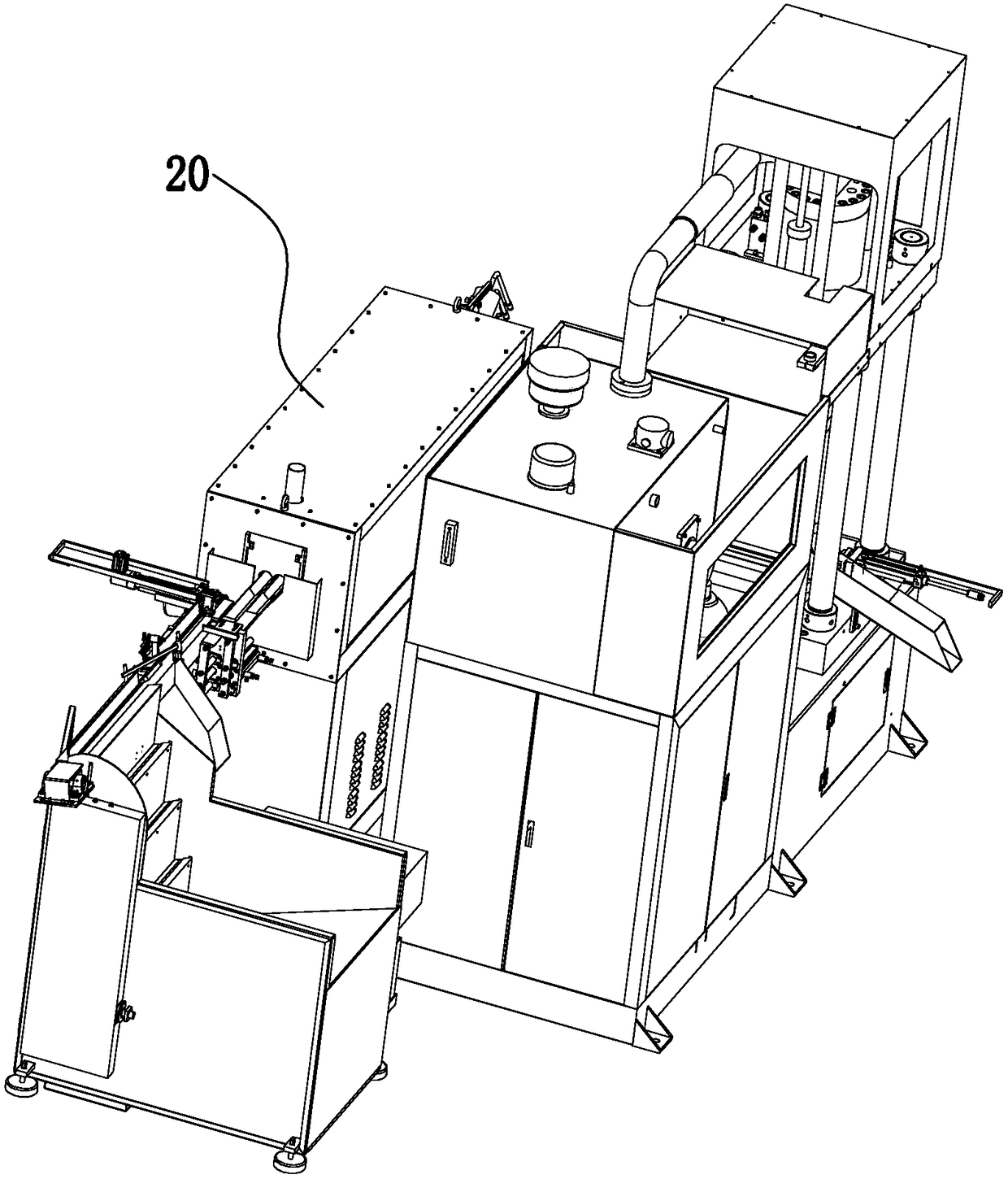
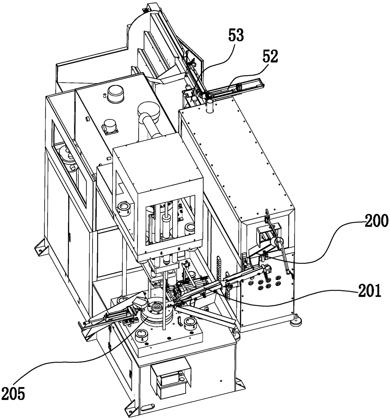
[0064] Example: such as Figure 1-3 As shown, a fully automatic vertical red punching equipment includes a loading frame assembly 50 for transferring workpieces, a raw material transmission device 51, a raw material pushing device 52 and a raw material feeding device 53; the raw material transmission device 51 is located on the upper The upper end of the material rack assembly 50; the position of the raw material pushing device 52 and the raw material feeding device 53 are corresponding; the raw material pushing device 52 and the raw material feeding device 53 are located at the end of the raw material transmission device 51; it is characterized in that: it also includes sequentially connected The red punch raw material heating furnace 20, the chute device 200, the conveying mechanism 201 and the processing mechanism 205; the raw material feeding device 53 is used to transport the workpiece to the red punch raw material heating furnace 20 for heating, and then transfer it to th...


PUM


Abstract

The invention relates to full-automatic vertical type red punching equipment. The equipment comprises a feeding rack assembly used for conveying workpieces, a raw material transmission device, a raw material pushing device and a raw material conveying device. The raw material transmission device is located at the upper end of the feeding rack assembly; the raw material pushing device and the raw material conveying device correspond to each other in position; and the raw material pushing device and the raw material conveying device are located at the end of the raw material transmission device.The equipment further comprises a red punching raw material heating furnace, a sliding chute device, a conveying mechanism and a machining mechanism which are connected in sequence. The full-automatic vertical type red punching equipment of a vertical structure is small in occupied space and high in automation degree. A protective cover and an observation groove are formed so that the personal safety of workers during machining can be ensured. Meanwhile, the working condition of the machining equipment can be observed at any time through the observation groove, the structure is simple, and the working process is safe and reliable.

Description

technical field [0001] The invention belongs to the technical field of mechanical equipment, and in particular relates to a fully automatic vertical red punching equipment. Background technique [0002] The specific processing method of the red punching process is to heat the brass rod or iron rod until it is red, and then put it into the hot stamping die of the punching machine for one-time extrusion molding. In the ordinary production process, the operator needs to clamp the heated brass rod or iron rod and other workpieces to the punching machine before processing. [0003] In the patent document with the authorized announcement number CN203438577U, an automatic red punching machine is disclosed. Although the traditional operation method has been changed, the structure described in the document is too complicated, there are too many transmission parts and control parts, and the control accuracy is not high. One piece of equipment needs to be operated by a special person,...

Claims


Application Information

Patent Timeline
Patent Type & Authority Applications(China)
IPC IPC(8): B21C23/21B21C33/00B21C31/00B21C29/00B21C23/18B07C5/34B07C5/36
CPCB07C5/34B07C5/362B21C23/18B21C23/212B21C29/003B21C31/00B21C33/00Y02P70/10
Inventor 沈信延
Owner 彪马集团有限公司
Why Eureka
Try Eureka