An electrorheological damper

A damper and electrorheological technology, applied in the direction of shock absorbers, shock absorbers, springs/shock absorbers, etc., can solve problems such as electromagnetic force decay, and achieve increased effective length, high integration, and simple structural design Effect

Active Publication Date: 2020-04-21
NANJING UNIV OF SCI & TECH
View PDF1 Cites 0 Cited by
  • Summary
  • Abstract
  • Description
  • Claims
  • Application Information

AI Technical Summary

Problems solved by technology

[0007] The purpose of the present invention is to provide an electrorheological damper, which solves the problem of electromagnetic force decay after heat accumulation of the damper actively controlled by electromagnetic force, and achieves a larger control range of damping force with little change in structural size

Method used


Image

  • An electrorheological damper
  • An electrorheological damper
  • An electrorheological damper

Examples


Embodiment Construction

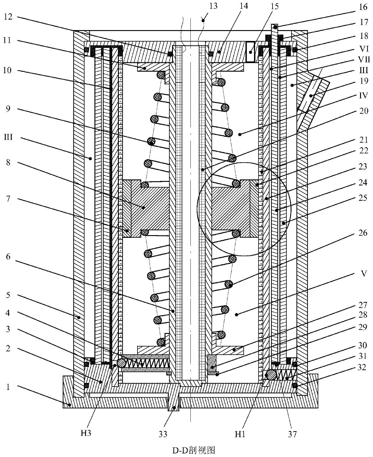
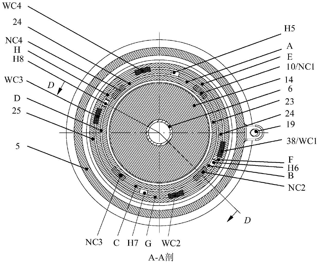
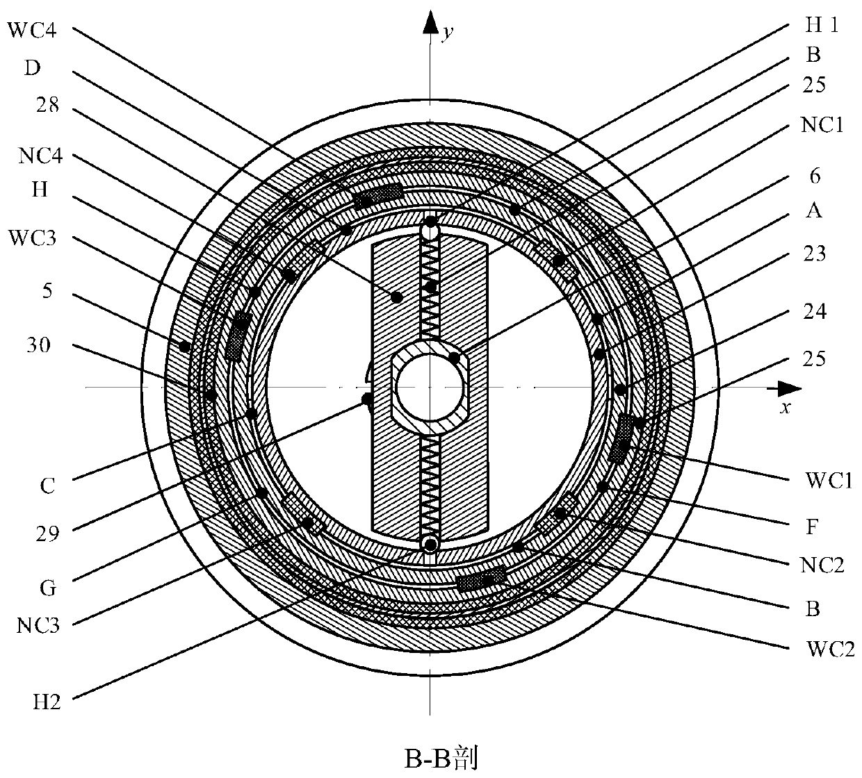
[0030] The electrorheological damper is used to control the need for active damping force when the piston of the cylinder moves relative to the cylinder under the action of an external force. The present invention will be further described in detail below in conjunction with the accompanying drawings. The purpose is to help those skilled in the art understand the concept and technical solution of the present invention. have a more complete, accurate and in-depth understanding, and facilitate its implementation, with a structure such as figure 1 shown.

[0031] combine Figure 1 to Figure 11 , the electrorheological damper of the present invention includes an inner negative plate assembly, a piston assembly, a bottom cover 1, an outer cylinder 5, a positive plate mounting seat 14, a negative plate mounting seat 2, M positive plate assemblies, and N outer negative plates components, M≥1, N≥0, wherein the inner negative plate assembly, the piston assembly, M positive plate assem...


PUM


Abstract

The invention discloses an electro rheological damper. The electro rheological damper comprises an inner negative plate assembly, a piston assembly, a bottom cover 1, an outer cylinder, a positive plate mounting seat, a negative plate mounting seat, M positive plate assemblies and N outer negative plate assemblies. Positive and negative plates form a multi-layer cylindrical cavity, a damping characteristic is formed after applying a high-voltage direct current electric field, high-voltage insulating plastic strips are arranged between the pole plates to control gaps of the pole plates, and a plurality of independent chambers are isolated for damping control in different flow directions. Return springs in the piston assembly are used for restoring a piston to the intermediate position and providing a buffer function. A closed-loop magnetic circuit consisting of a HALBACH array, an electromagnetic coil winding, the piston and a central shaft realizes the measurement of the piston position, and is used as a position or a velocity signal of an oil cylinder piston for the control need of the electro rheological variable damping force. The electro rheological damper is connected in series between an oil cylinder and an energy accumulator through the pipeline connection, is suitable for the environment with strict installation space requirements, and is especially suitable for the vibration damping environment with active control requirements.

Description

technical field [0001] The invention belongs to the technical field of dampers, in particular to an electrorheological damper, which is suitable for industries such as vehicles, weapons, aviation, ships, industries, buildings, and bridges. Background technique [0002] When loads such as earthquakes, random wind loads, uneven road surfaces, engine excitation, and artillery launch impact force act on the structure, the structure will absorb a large amount of external energy, and the structure will have a structural dynamic response due to forced vibration. When the structural response exceeds its own deformation capacity, the structure is destroyed or damaged, such as the collapse of houses under the action of earthquakes, the fracture of pull cables under random wind loads, and the cracking of frame structures under the excitation of uneven road surfaces. In order to ensure the safety of the structure, the researchers put forward the concept of structural vibration control, ...

Claims


Application Information

Patent Timeline
Patent Type & Authority Patents(China)
IPC IPC(8): F16F9/53
CPCF16F9/532
Inventor 谢继鹏杨国来陈飞
Owner NANJING UNIV OF SCI & TECH
Why Eureka
Try Eureka