Ocular lens and display device

A display device and eyepiece technology, applied in the optical field, can solve the problems of large chromatic aberration and distortion, the inability to meet the thinning and high performance of head-mounted equipment, and achieve the effect of reducing physical distance, reducing size, and realizing light and thin

Pending Publication Date: 2018-12-07
ZHEJIANG SUNNY OPTICAL CO LTD
View PDF7 Cites 9 Cited by
  • Summary
  • Abstract
  • Description
  • Claims
  • Application Information

AI Technical Summary

Problems solved by technology

[0004] In order to achieve higher magnification, it is generally required that the eyepiece for VR imaging has a longer working distance, and has greater chromatic aberration and distortion. However, this cannot meet people's needs for thinner, lighter and higher-performance headsets.

Method used


Image

  • Ocular lens and display device
  • Ocular lens and display device
  • Ocular lens and display device

Examples


Embodiment 1

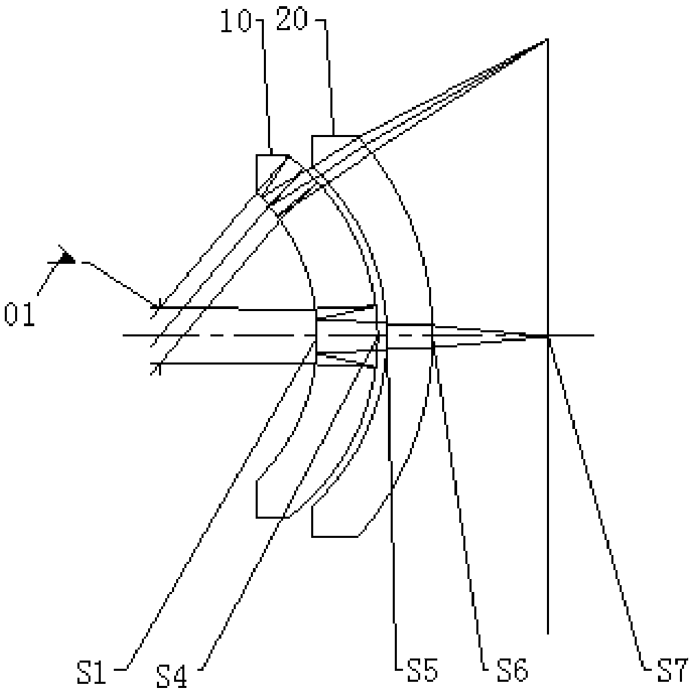
[0082] In the direction close to the image source, the eyepiece consists of a reflective circular polarizer, a first lens 10, a 1 / 4 lambda wave plate, a reflective linear polarizer and a second lens 20 arranged in sequence. For details, please refer to figure 1 , the figure does not show the radial linear polarizer, reflective circular polarizer and 1 / 4λ wave plate.

[0083] The optical path of this embodiment can refer to figure 1 As shown, from the side of the human eye 01, the light passes through S1 in sequence, and after two reflections in the middle, it reaches the imaging surface S7. The parameters of each optical surface are shown in Table 1, wherein, S1 represents the first surface of the first lens 10, S2 represents the reflective surface of the reflective linear polarizer, S3 represents the reflective surface of the reflective circular polarizer, and S4 represents the first The second surface of the lens 10, S5 represents the first surface of the second lens 20, S6...

Embodiment 2

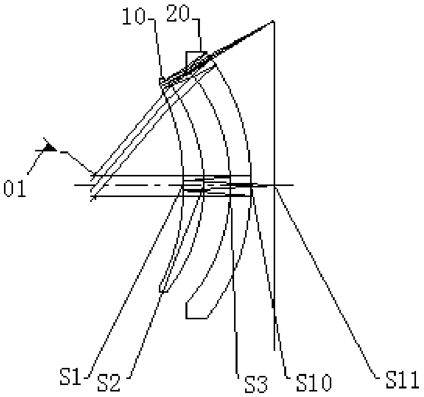
[0090] In the direction close to the image source, the eyepiece consists of a reflective circular polarizer, a first lens 10, a 1 / 4 lambda wave plate, a second lens 20 and a reflective linear polarizer arranged in sequence. For details, please refer to image 3 , the figure does not show the radial linear polarizer, reflective circular polarizer and 1 / 4λ wave plate.

[0091] The optical path of this embodiment can refer to image 3 As shown, from the side of the human eye 01, the light passes through S1 in sequence, goes through two reflections in the middle, and reaches the imaging surface S11. The parameters of each optical surface are shown in Table 2, wherein, S1 represents the first surface of the first lens 10, S2 represents the second surface of the first lens 10, S3 represents the first surface of the second lens 20, and S4 represents the reflection type The reflective surface of the linear polarizer, S5 represents the first surface of the second lens 20, S6 represent...

Embodiment 3

[0099] In the direction close to the image source, the eyepiece consists of a reflective circular polarizer, a first lens 10, a 1 / 4 lambda wave plate, a reflective linear polarizer and a second lens 20 arranged in sequence. For details, please refer to Figure 5 , the figure does not show the radial linear polarizer, reflective circular polarizer and 1 / 4λ wave plate.

[0100] The optical path of this embodiment can refer to Figure 5 As shown, from the side of the human eye 01, the light passes through S1 in sequence, and after two reflections in the middle, it reaches the imaging surface S9. The parameters of each optical surface are shown in Table 3, wherein S1 represents the first surface of the first lens 10, S2 represents the second surface of the first lens 10, S3 represents the reflective surface of the reflective linear polarizer, and S4 represents the first surface of the first lens 10. The second surface of the lens 10, S5 represents the reflective surface of the re...


PUM


Abstract

The invention provides an ocular lens and a display device. The ocular lens comprises the components of a lens assembly with positive focal power or negative focal power, wherein the lens assembly comprises at least two lenses, in a direction of approaching an image source, a first lens and a second lens are successively arranged; a reflective linear polaroid which is arranged on one surface, which is next to the image source, of the first lens, or the surface of the second lens; a reflective circular polarid which is arranged on the surface of the first lens, wherein the reflective circular polaroid is arranged at one side, which is far from the image side, of the reflective linear polarid; and a quarter lambda wave plate which is arranged between the reflective liner polaroid and the reflective circular polaroid, wherein the first lens has positive focal power or negative focal power, the second lens has the negative focal power, the Abbe number Vd1 of the material of the first lensis higher than 50, and the Abbe number Vd2 of the material of the second lens is lower than 30. The ocular lens has advantages of relatively short working distance, relatively small lens size, low thickness of the lens and relatively high imaging quality.

Description

technical field [0001] The present application relates to the field of optics, in particular to an eyepiece and a display device. Background technique [0002] In recent years, with the rapid development of computer technology, virtual reality (VR) has become more and more mature, and it has more and more applications in professional and consumer fields. As the core optical component of the head-mounted display device, the VR eyepiece directly affects the application and experience of the device, so it has high requirements for the imaging quality and appearance quality of the eyepiece. [0003] In order to provide a good user experience, VR wearable devices need to achieve better field of view, eye movement range, high-quality imaging effects, and small-sized ultra-thin structures. Optimal design of the lens group. [0004] In order to achieve higher magnification, it is generally required that the eyepiece for VR imaging has a longer working distance, and has greater chr...

Claims


Application Information

Patent Timeline
Patent Type & Authority Applications(China)
IPC IPC(8): G02B25/00G02B13/00G02B27/00G02B27/01
CPCG02B13/0015G02B25/001G02B27/0025G02B27/0101G02B27/0172G02B27/286G02B2027/0116G02B2027/011G02B9/10G02B9/16G02B17/0856G02B9/04
Inventor 娄琪琪宋立通
Owner ZHEJIANG SUNNY OPTICAL CO LTD
Why Eureka
Try Eureka