
A method to improve the safety of outdoor power distribution

A safe, high-voltage power distribution cabinet technology, applied in substation/distribution device housing, substation/switchgear cooling/ventilation, current collectors, etc. Poor, unfavorable outdoor use, etc., to achieve the effect of convenient and quick maintenance, improved safety, and safe use

Active Publication Date: 2020-01-24
扬州正扬电力科技有限公司 +1
View PDF8 Cites 0 Cited by
  • Summary
  • Abstract
  • Description
  • Claims
  • Application Information

AI Technical Summary

Problems solved by technology

[0003] However, the traditional high-voltage power distribution cabinet has poor heat dissipation performance during use. When the electrical equipment is damaged, it is inconvenient to repair the internal electrical components. The sealing performance of the cabinet body is poor, which is not conducive to outdoor use.
[0004] At the same time, when the outdoor temperature is high, the temperature inside the high-voltage power distribution cabinet also rises correspondingly, which may easily cause fires in the internal circuits of the high-voltage power distribution cabinet, thereby posing certain safety hazards. The solutions adopted in the prior art Generally, ventilation holes are added to the high-voltage power distribution cabinet, and fireproof materials are used at the same time, which avoids the possibility of fire in the high-voltage power distribution cabinet to a certain extent, but there are still certain potential safety hazards. When the high-voltage power distribution cabinet fires, People can only watch the fire and do nothing

Method used


Image

  • A method to improve the safety of outdoor power distribution
  • A method to improve the safety of outdoor power distribution
  • A method to improve the safety of outdoor power distribution

Examples


Embodiment Construction

[0030] In order to make the technical means, creative features, goals and effects achieved by the present invention easy to understand, the present invention will be further described below in conjunction with specific embodiments.

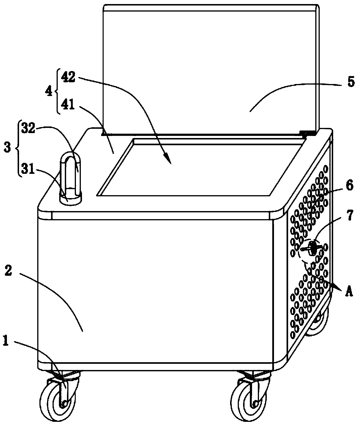
[0031] like figure 1 and Figure 4 As shown, a method for improving the safety of outdoor power distribution described in the present invention includes the following steps:

[0032] S1, install solar panels on the top of the high-voltage power distribution cabinet. On the one hand, the solar panels shade the high-voltage power distribution cabinet from the sun and rain, and on the other hand, they are used to charge the battery;

[0033] The batteries in S2 and S1 are electrically connected to the controller. A fan is installed on the side of the high-voltage power distribution cabinet in S1. The fan is electrically connected to the controller. A temperature sensor is installed outside the high-voltage power distribution cabinet. The sensor is ...


PUM


Abstract

The invention relates to a method for improving the security of outdoor power distribution, and relates to the field of power distribution cabinets. The method comprises the following steps that S1) asolar cell panel is installed in the top of a high-voltage power distribution cabinet, and charges a storage battery; S2) the storage battery is electrically connected with a controller, a fan is installed in the lateral side of the high voltage power distribution cabinet, and electrically connected with the controller, and a temperature sensor is installed outside the high voltage power distribution cabinet, and used to monitor the temperature of the high voltage power distribution cabinet; and S3) an automatic dry powder fire extinguisher is installed in the lateral side of the high voltagepower distribution cabinet and electrically connected with the controller, when the temperature detected by the temperature sensor in S2 of the high voltage power distribution cabinet reaches a ratedtemperature, the controller controls the automatic fire extinguisher to carry out fire extinguishing on the high voltage power distribution cabinet. Thus, the high voltage power distribution cabinetitself is improved via external equipment protection, the rate of fire hazards of the high voltage power distribution cabinet is reduced greatly, and the using effect is better.

Description

technical field [0001] The invention relates to the field of power distribution cabinets, in particular to a method for improving the safety of outdoor power distribution. Background technique [0002] With the rapid development of the power industry, distribution cabinets for installing electrical instruments are essential. As the name implies, high-voltage distribution cabinets are power distribution equipment used for power distribution, control, measurement and cable connection in power supply systems. General power supply bureaus , Substations use high-voltage switchgear, and then the low-voltage side of the transformer is stepped down to lead to the low-voltage distribution cabinet. The low-voltage distribution cabinet is connected to each power distribution panel, control box, and switch box. Inside, some switches, Circuit breakers, fuses, buttons, indicators, meters, wires and other protective devices are assembled into a power distribution device that meets the desi...

Claims


Application Information

Patent Timeline
Patent Type & Authority Patents(China)
IPC IPC(8): H02B1/56H02B1/28H02B1/30H02J7/35A62C37/40A62C3/16
CPCA62C3/16A62C37/40H02B1/28H02B1/30H02B1/565H02J7/35
Inventor 张庆云
Owner 扬州正扬电力科技有限公司
Learn More