A variable permanent magnet reluctance motor

A reluctance motor, variable technology, applied to synchronous motors with stationary armatures and rotating magnets, magnetic circuits, synchronous machines, etc., can solve the problems of low speed and low power operation, low power factor, demagnetization, etc. Achieve the effect of improving comprehensive performance, wide field weakening range and good adaptability

Active Publication Date: 2020-11-24
杨世国
View PDF6 Cites 0 Cited by
  • Summary
  • Abstract
  • Description
  • Claims
  • Application Information

AI Technical Summary

Problems solved by technology

[0002] The rapid development and popularization of electric vehicles has put forward higher and higher requirements for the performance of drive motors. For motors, one of the key "three electric technologies", most of them currently use PMSM permanent magnet synchronous motors, IM asynchronous induction motors, and SRM Switched reluctance motors, the industry generally believes that these three types of motors have their own advantages and disadvantages: permanent magnet synchronous motors have high specific power, good speed regulation performance, and stable operation, but they may demagnetize, and high-grade rare earth magnets are required. Small volume and weight, high comfort passenger cars and electric aircraft, etc.; asynchronous induction motors have good robustness, but have large weight and volume, low power factor, low speed and low power operation efficiency, and are suitable for large power and large models. Locomotives; switched reluctance motors appeared late, with a wide speed range and high reliability, but the torque fluctuations are large, and the power density is not as good as that of permanent magnet synchronous motors, and is being improved
In addition, when the rotor moves out, the inductance becomes smaller, and the axial resistance against movement is generated. The size is related to the operating current of the winding, and it is not easy to adjust the control parameters.

Method used


Image

  • A variable permanent magnet reluctance motor
  • A variable permanent magnet reluctance motor
  • A variable permanent magnet reluctance motor

Examples


Embodiment Construction

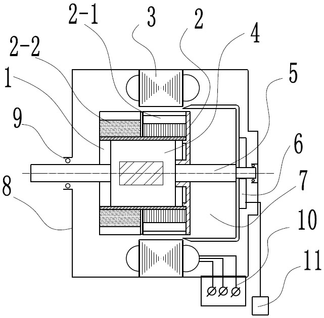
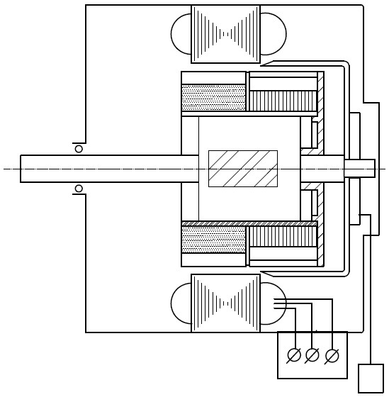
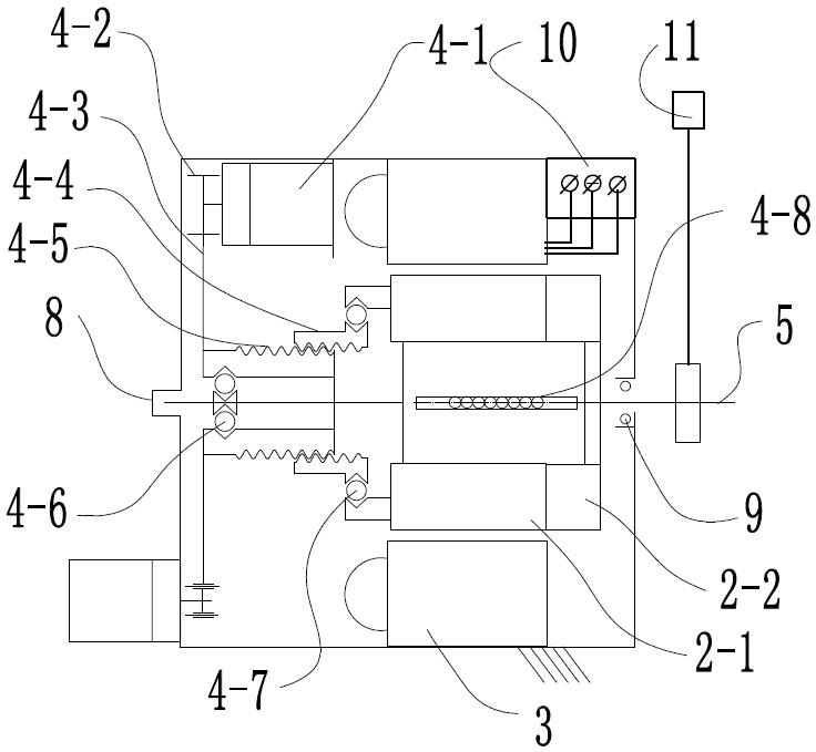
[0029] The present invention will be further described below in conjunction with an example of a variable permanent magnet reluctance motor with 3 phases, 12 slots and 8 poles. For the configuration of stator and rotor slot poles, refer to the attached Figure 7 , the default length unit is mm, motor parameters: M=3, q=12, 2p=8, stator core diameter Da=135, air gap diameter D=85, stack thickness L=60; rotor diameter Dr=84 , 2p=8, the core length of the permanent magnet rotor section is 50, the additional reluctance rotor section is 30, the total length of the rotor is 80, the design rotor movement range is 30, the mechanical magnetic field is about 60%, and the reluctance rotor is just right under the highest speed condition Move completely into the stator. The total length of the available rotor is 1.6 times the length of the stator.

[0030] In this example, the stator has 0.5 slots for each pole and each phase, which is a fractional slot structure, including 4 unit motors...


PUM


Abstract

A VPMRM variable permanent magnetism reluctance motor comprises a stator, a mobile rotor, and a speed change mechanism that moves the rotor; the features are that the VPMRM motor designs to add a reluctance rotor segment on an existing permanent magnetism rotor, thus forming the high performance permanent magnetism reluctance brushless motor (VPMRM) that combines a permanent magnetism motor with areluctance motor; the linkage and inductance parameters of the VPMRM motor are continuous variable, and the mechanical type torque adaptive speed regulation or intelligent control speed regulation ofthe motor can be realized; the valid length of the permanent magnetism rotor is approximately the same with a stator core length; the reluctance rotor length is <= the permanent magnetism rotor and equal to a rotor axially moving distance, wherein the rotor total length is <= two times of the stator length; a linkage adjusting mechanism capable of enabling the rotor to move with respect to the axis is arranged between the rotor and the axis. The VPMRM motor is simple and feasible, and the comprehensive properties thereof are higher than that of asynchronous, synchronization or switch reluctance motors of the same cost in the prior art.

Description

technical field [0001] The invention belongs to the technical field of motors, in particular to a permanent magnet brushless motor which needs to operate at high speed and high efficiency under variable working conditions. Background technique [0002] The rapid development and popularization of electric vehicles has put forward higher and higher requirements for the performance of drive motors. For motors, one of the key "three electric technologies", most of them currently use PMSM permanent magnet synchronous motors, IM asynchronous induction motors, and SRM Switched reluctance motors, the industry generally believes that these three types of motors have their own advantages and disadvantages: permanent magnet synchronous motors have high specific power, good speed regulation performance, and stable operation, but they may demagnetize, and high-grade rare earth magnets are required. Small volume and weight, high comfort passenger cars and electric aircraft, etc.; asynchro...

Claims


Application Information

Patent Timeline
Patent Type & Authority Patents(China)
IPC IPC(8): H02K21/14H02K21/02H02K1/24H02K1/27
CPCH02K1/246H02K1/2706H02K21/022H02K21/14H02K2201/03H02K2201/18H02K2213/03
Inventor 杨世国
Owner 杨世国
Why Eureka
Try Eureka