Shoulder joint implant

An implant and shoulder joint technology, applied in the medical field, can solve the problems of troublesome rotator cuff tear treatment, high technical difficulty, and high price, and achieve the effect of restoring normal biomechanical properties, great application prospects, and high success rate

Pending Publication Date: 2018-12-11
张文涛
View PDF0 Cites 3 Cited by
  • Summary
  • Abstract
  • Description
  • Claims
  • Application Information

AI Technical Summary

Problems solved by technology

[0003] In order to overcome the deficiencies of the prior art, the present invention discloses a shoulder joint implant, which is used t...

Method used


Image

  • Shoulder joint implant
  • Shoulder joint implant
  • Shoulder joint implant

Examples


Embodiment 1

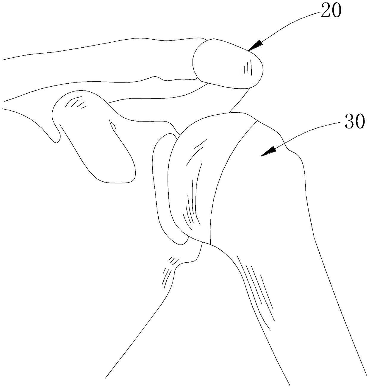
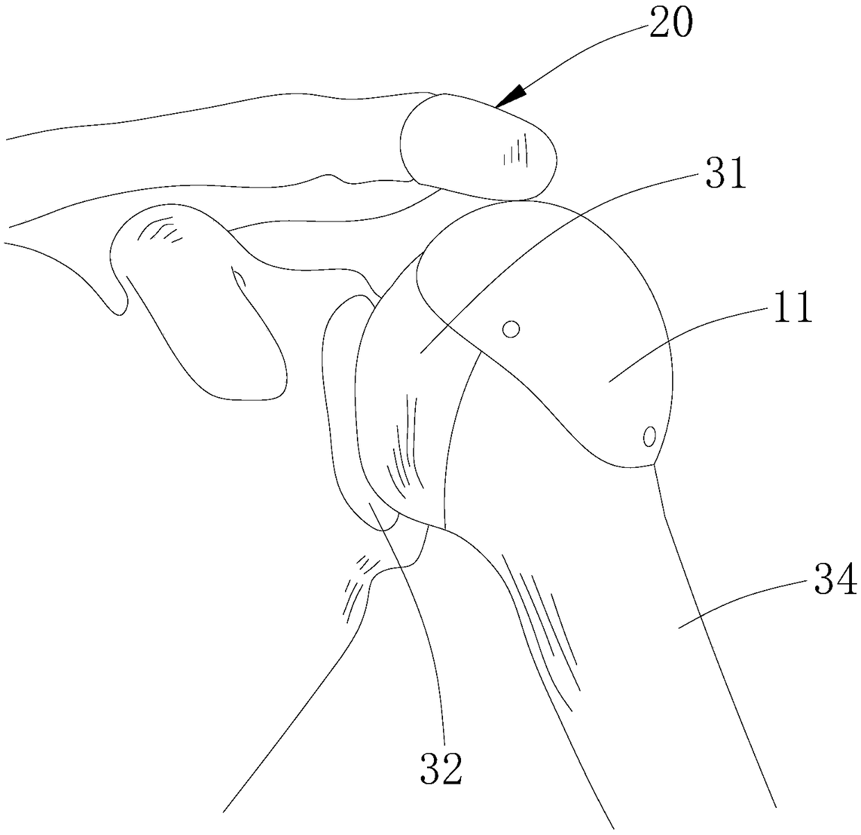
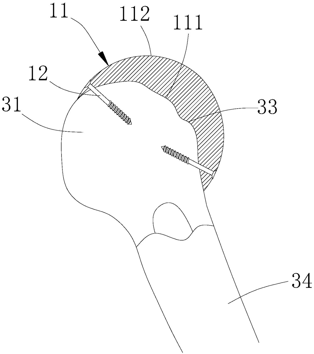
[0033] see Figure 1-3 , Embodiment 1 of the present invention provides a shoulder joint implant, which is used to maintain and increase the distance between the humeral head and the shoulder front and increase the distance between the greater tuberosity of the humerus and the shoulder front when the shoulder is abducted. The joint implant includes a solid cover 11 arranged between the shoulder 20 and the humerus end 30 and fixedly connected to the humerus end 30. The solid cover 11 has a first surface 111 fitted to the humerus end 30 and The second surface 112 disposed away from the humerus end 30 directly or indirectly abuts against the lower surface of the shoulder 20 .

[0034] In this design, through the solid cover 11 being fixedly connected to the humerus end 30, the second surface 112 of the solid cover 11 abuts against the lower surface of the shoulder 20 directly or indirectly. In this way, the distance between the humerus end 30 and the lower surface of the shoulde...

Embodiment 2

[0043] see Figure 5 The difference between the shoulder joint implant provided in Embodiment 2 of the present invention and the shoulder joint implant provided in Embodiment 1 is that the structure of the solid cover is different, specifically embodied in: the solid cover 21 provided in Embodiment 2 of the present invention Comprising an inner lining 213 and an outer lining 214, the inner lining 213 is a metal body fixed to the end of the humerus end 30 by bonding or screwing, the outer lining 214 is a ceramic body or a high molecular polyethylene body, and the inner side wall of the outer lining 214 It is fixed on the outer surface 215 of the inner liner 213 facing away from the humerus end 30 . With this design, by setting the metal lining, on the one hand, it can facilitate the fixing of the screw, on the other hand, it can make the solid cover more firmly fixed at the end of the humerus, reduce the possibility of its failure, and prolong the service life.

[0044] Prefer...

Embodiment 3

[0047] see Figure 6-11 The difference between the shoulder joint implant provided in the third embodiment of the present invention and the shoulder joint implant provided in the first embodiment is that the shoulder joint implant also includes a lower surface fixed on the shoulder front 20 to prevent shoulder The wear-resistant part 14 is worn by the front 20 , and the second surface 112 has an abutment portion abutting against the wear-resistant part 14 . It can be understood that since the humerus end 30 is in a relatively movable state relative to the shoulder 20, the abutting portion changes. With this design, the wear-resistant part 14 can prevent the shoulder 20 from being severely worn when the solid cover 11 is used for a long time, resulting in thinning of the shoulder 20 and prone to fracture of the shoulder 20 . Specifically, the wear-resistant piece 14 may be a ceramic layer or a high molecular polyethylene layer or a metal layer.

[0048] Preferably, the wear-r...


PUM


Abstract

The invention discloses a shoulder joint implant for maintaining and properly increasing the distance between a humeral head and an acromion and increasing the distance between a humerus greater tubercle and the acromion at shoulder abduction. The shoulder joint implant comprising a solid cover is characterized in that the solid cover disposed between the end portion of the humerus and the acromion is fixedly connected with the end portion of the humerus; the solid cover is provided with a first surface and a second surface, wherein the first surface fits the end portion of the humerus, and the second surface is disposed with the back to the end portion of the humerus; the second surface directly or indirectly abuts the lower surface of the acromion. With the end portion of the humerus fixedly connected with the solid cover and the solid cover capable of maintaining the distance between the end portion of the humerus and the lower surface of the acromion, the shoulder joint implant hasthe advantages of preventing the pain caused by the impact between the acromion and the end portion of the humerus, restoring normal biomechanical properties of the shoulder joint of a patient, effectively reducing extrusion on surrounding tissues due to the fact that the solid cover is a solid structure and the shape is small when pressed by force, and reducing shoulder discomfort.

Description

technical field [0001] The invention relates to the medical field, in particular to a shoulder joint implant. Background technique [0002] Rotator cuff tear is a common cause of shoulder pain, limited mobility and dysfunction. Rotator cuff tear leads to a series of shoulder inflammation and affects the quality of daily life, such as shoulder pain, and caused by shoulder pain Can't sleep at night, can't comb hair, and female patients can't take off their bras, etc. There are a series of surgical methods for its treatment plan, such as muscle tendon transplantation, upper joint capsule reconstruction or reverse shoulder replacement surgery, etc. However, muscle tendon transplantation will destroy the normal structure and destroy anatomy; reverse shoulder replacement is expensive and technically difficult Popularity; while the scientific evidence for upper joint capsule reconstruction needs to be strengthened. Contents of the invention [0003] In order to overcome the def...

Claims


Application Information

Patent Timeline
IPC IPC(8): A61F2/40
CPCA61F2/4014A61F2002/4022
Inventor 张文涛
Owner 张文涛
Why Eureka
Try Eureka