
A refractory shield cable for computer control

A fire-resistant computer and shielded cable technology, used in insulated cables, communication cables, cables, etc., can solve major accidents, signal distortion, equipment malfunction and other problems, achieve high safety, improve friction, and increase corrosion resistance. Effect

Inactive Publication Date: 2018-12-11
庄粉香
View PDF0 Cites 0 Cited by
  • Summary
  • Abstract
  • Description
  • Claims
  • Application Information

AI Technical Summary

Problems solved by technology

[0002] Computer control cables usually use good electric conductors as shielding materials, which have obvious anti-interference effect on high-frequency signals, but for some low-frequency and strong electromagnetic field interference areas, ordinary computer control cables are no longer competent for normal signal transmission and anti-interference The high requirements of high requirements will often cause some signal distortions, which will lead to equipment malfunction and major accidents in severe cases; therefore, it is necessary to design a new structure for the computer control cable structure and materials, so that the computer control cable can operate in high and low frequency bands, It has strong anti-interference performance in the environment of high-intensity electromagnetic field, and at the same time avoids the contact of different metal materials, prevents electrochemical reaction due to potential difference, and ensures the service life of the product

Method used


Image

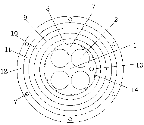
  • A refractory shield cable for computer control
  • A refractory shield cable for computer control
  • A refractory shield cable for computer control

Examples


Embodiment Construction

[0017] The preferred embodiments of the present invention will be described below in conjunction with the accompanying drawings. It should be understood that the preferred embodiments described here are only used to illustrate and explain the present invention, and are not intended to limit the present invention.

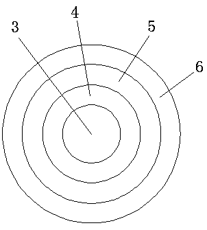
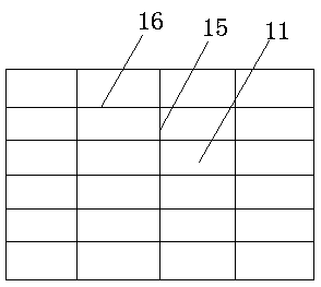
[0018] see Figure 1-Figure 3 , the present invention provides a technical solution:

[0019] A fire-resistant shielded cable for computer control, including a cable assembly 1, the inner cavity of the cable assembly 1 is provided with a wire core 2, the center of the wire core 2 is provided with a metal conductor 3, and the outside of the metal conductor 3 is provided with a tape layer 4 , the outer side of the tape layer 4 is bonded with a phase-separated shielding layer 5 through an adhesive, which can shield multiple cables, so that the multiple wires working at the same time in the cable will not affect each other, ensuring accurate information transmission Th...


PUM


Abstract

The invention relates to a refractory shield cable for computer control. The cable includes a cable assembly, A cable core is arranged in the inner cavity of the cable assembly, A metal conductor is arranged at that center of the wire core, A tape clad layer is arranged on that outside of the metal conductor, A phase separation shield layer is bonded on the outer side of the cladding layer throughan adhesive, At that outside of the phase-separated shield lay, an insulating ribbon is bonded by an adhesive, A fill layer is arranged on the outside of the cable assembly, A cladding layer is arranged on the outer side of the filling layer, A shield layer is adhered to that outside of the cladding layer through an adhesive, At that outer side of the shield layer, a fireproof filling layer is bonded with an adhesive, A reinforcing layer is bonded on the outside of the fireproof filling layer through an adhesive, and an abrasion-resistant layer is bonded on the outside of the reinforcing layer through an adhesive. The electric conductive unit runs most stably and reliably and has the most ideal use effect through the coordinated use of the layers, so that the overall fireproof performanceand the shielding performance of the cable are good, the overall strength is high, and the overall service life of the product is long and the safety is high.

Description

technical field [0001] The invention relates to a fire-resistant shielded cable for computer control, which belongs to the technical field of computer cables. Background technique [0002] Computer control cables usually use good electric conductors as shielding materials, which have obvious anti-interference effect on high-frequency signals, but for some low-frequency and strong electromagnetic field interference areas, ordinary computer control cables are no longer competent for normal signal transmission and anti-interference The high requirements of high requirements will often cause some signal distortions, which will lead to equipment malfunction and major accidents in severe cases; therefore, it is necessary to design a new structure for the computer control cable structure and materials, so that the computer control cable can operate in high and low frequency bands, It has strong anti-interference performance in the environment of high-intensity electromagnetic field...

Claims


Application Information

Patent Timeline
Patent Type & Authority Applications(China)
IPC IPC(8): H01B7/17H01B7/36H01B7/18H01B11/00
CPCH01B7/17H01B7/183H01B7/1835H01B7/184H01B7/1865H01B7/1875H01B7/361H01B11/005
Inventor 庄粉香
Owner 庄粉香
Learn More