Internal drive-external power generation integrated pulse generator power supply

A generator and internal drive technology, applied in the direction of electromechanical devices, electrical components, electric components, etc., can solve the problems of increasing the axial length of the system, torque impact of couplings, poor structural compactness, etc., and achieve simplified axial length, Effects of improving compactness, increasing energy density and power density

Inactive Publication Date: 2018-12-11
HARBIN INST OF TECH
View PDF5 Cites 4 Cited by
  • Summary
  • Abstract
  • Description
  • Claims
  • Application Information

AI Technical Summary

Problems solved by technology

[0004] The purpose of the present invention is to solve the problem that the existing pulse generator and prime mover are connected through a ...

Method used


Image

  • Internal drive-external power generation integrated pulse generator power supply

Examples


specific Embodiment approach 1

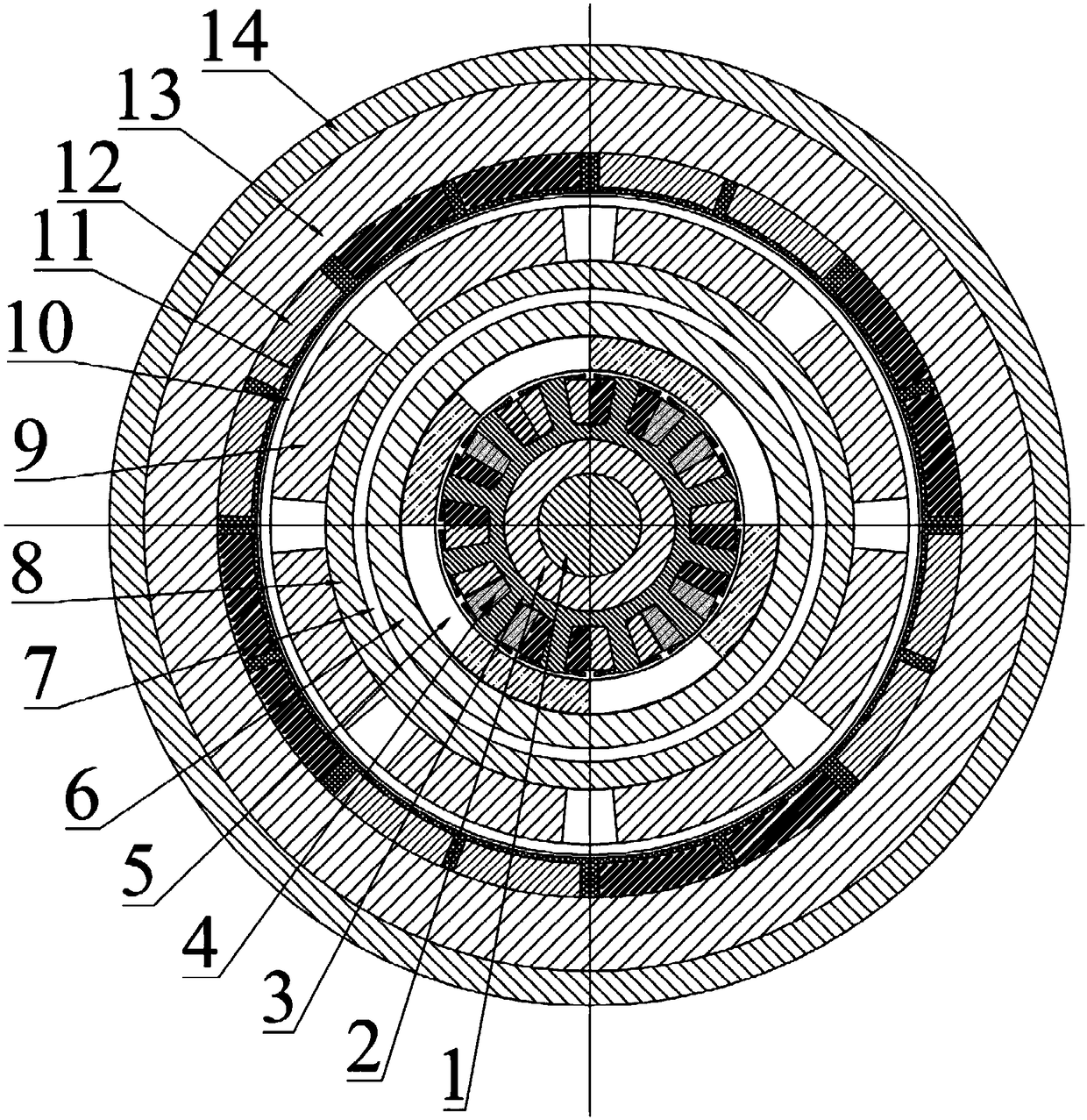
[0017] Specific implementation mode one: refer to figure 1 Describe this embodiment in detail, the internal drive-external power generation integrated pulse generator power supply described in this embodiment includes a casing 14, a magnetic isolation ring 7, a motor and a generator,

[0018] A generator is arranged inside the casing 14, and a motor is arranged inside the generator, and the electromagnetic field is separated by a magnetic isolation ring 7 between the generator and the motor;

[0019] The motor includes a rotating shaft 1, a motor stator yoke 2, a motor stator core 3 and a motor rotor core 6,

[0020] The motor stator yoke 2 is fixed on the outer peripheral surface of the rotating shaft 1. The motor stator core 3 is arranged on the outer peripheral surface of the motor stator yoke 2. The outer surface of the motor stator core 3 is uniformly distributed with rotor teeth along the circumferential direction. The rotor teeth are wound with The motor armature windi...

Embodiment 1

[0026] The internal drive-external power generation integrated pulse generator power supply is characterized in that it includes a casing 14, a magnetic isolation ring 7, a motor and a generator,

[0027] A generator is arranged inside the casing 14, and a motor is arranged inside the generator, and the electromagnetic field is separated by a magnetic isolation ring 7 between the generator and the motor;

[0028] The motor includes a rotating shaft 1, a motor stator yoke 2, a motor stator core 3 and a motor rotor core 6,

[0029] The motor stator yoke 2 is fixed on the outer peripheral surface of the rotating shaft 1. The motor stator core 3 is arranged on the outer peripheral surface of the motor stator yoke 2. The outer surface of the motor stator core 3 is uniformly distributed with rotor teeth along the circumferential direction. The rotor teeth are wound with An eight-pole three-phase motor armature winding 4, a motor rotor iron core 6 is arranged on the inner circular su...

specific Embodiment approach 2

[0033] Embodiment 2: This embodiment is a further description of the internal drive-external power generation integrated pulse generator power supply described in Embodiment 1. In this embodiment, the generator rotor yoke 8 is a non-magnetic material.


PUM


Abstract

An internal drive-external power generation integrated pulse generator power supply relates to the technical field of inertial energy storage pulse power supply. The invention aims at solving the problem that the prior pulse generator and the prime mover are connected through the coupling, the coupling is easy to be subjected to torque impact, the axial length of the system is increased, and the compactness of the structure is poor. A generator is arranged inside the casing, a motor is arranged inside the generator, an electromagnetic field is separated between the generator and the motor through a magnetic isolation ring, and the armature winding of the motor is connected with a three-phase alternating current to drive the rotor core of the motor to rotate, thereby driving the magnetic isolation ring and the rotor yoke of the generator to rotate to generate electric power. The iInternal drive-external power generation integrated pulse generator power supply is used to increase the energy density and power density of the system.

Description

technical field [0001] The invention relates to an integrated pulse generator power supply with internal drive and external power generation, and belongs to the technical field of inertial energy storage pulse power supply. Background technique [0002] The pulse generator, as an inertial energy storage pulse power supply, is driven by a prime mover. The pulse generator integrates inertial energy storage, electromechanical energy conversion and pulse shaping, and has the comprehensive advantages of "single component". It has the advantages of high energy density, high power density, suitable for repeated discharge, flexible pulse waveform adjustment, etc., and has a wide range of applications in military, industrial and civilian fields. [0003] The existing pulse generator and prime mover are connected through a coupling, which easily causes torque impact on the coupling, and increases the axial length of the system, resulting in poor structural compactness. Contents of ...

Claims


Application Information

Patent Timeline
IPC IPC(8): H02K39/00H02K7/20
CPCH02K7/20H02K39/00
Inventor 吴绍朋吴松霖田晨晨崔淑梅
Owner HARBIN INST OF TECH
Why Eureka
Try Eureka