A six-level circuit topology for a power conversion system

A technology of circuit topology and power conversion, applied in high-efficiency power electronic conversion, conversion of AC power input to DC power output, electrical components, etc., can solve the problem of large switching loss, difficult to eliminate dead zone effect, complex mode switch state switching, etc. question

Active Publication Date: 2018-12-11
NORTHEASTERN UNIV
View PDF3 Cites 2 Cited by
  • Summary
  • Abstract
  • Description
  • Claims
  • Application Information

AI Technical Summary

Problems solved by technology

[0004] In the current six-level research that has been proposed, there are still problems such as large swi

Method used


Image

  • A six-level circuit topology for a power conversion system
  • A six-level circuit topology for a power conversion system
  • A six-level circuit topology for a power conversion system

Examples


Embodiment 1

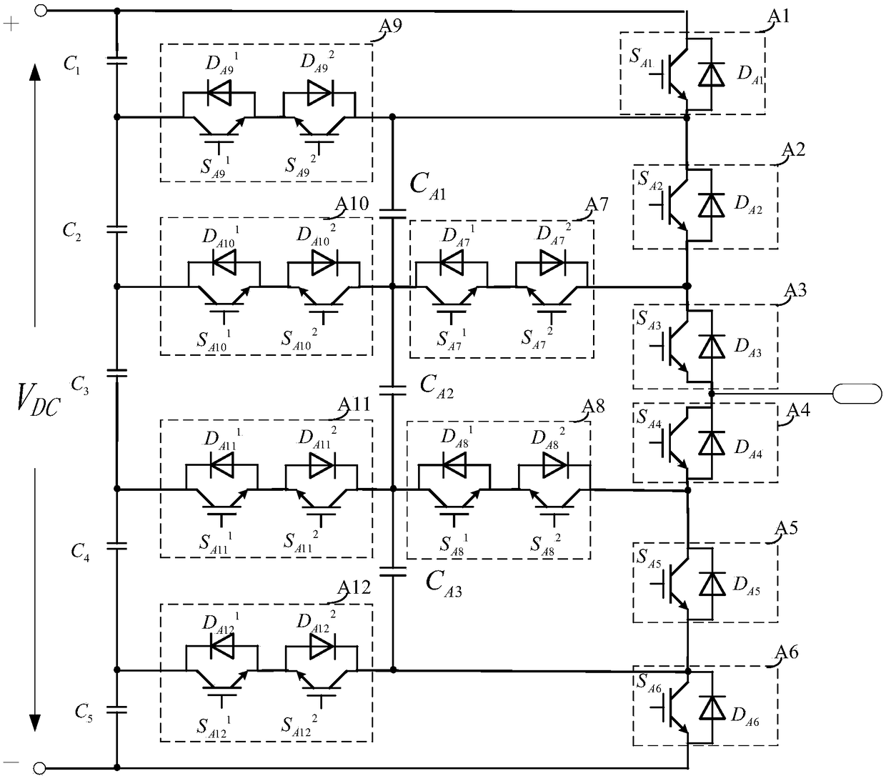
[0092] Such as figure 1 As shown, the present invention is a six-level circuit topology for power conversion systems, including twelve switching devices A1-A12, five bus capacitors C 1 ~C 5 and three clamping capacitors C A1 ~C A3 .

[0093] The six-level circuit topology includes a first bus capacitor C 1 ~ Fifth bus capacitor C 5 The left path composed of serial connections in the same direction in turn,

[0094] The right path composed of the first switching device A1 to the sixth switching device A6 connected in series in sequence,

[0095] Middle Road 1 composed of the ninth switching device A9,

[0096] The second middle circuit composed of the seventh switching device A7 and the tenth switching device A10 connected in series,

[0097] The middle circuit three composed of the eighth switching device A8 and the eleventh switching device A11 connected in series,

[0098] A middle circuit four composed of the twelfth switching device A12.

[0099] In said right pa...

Embodiment 2

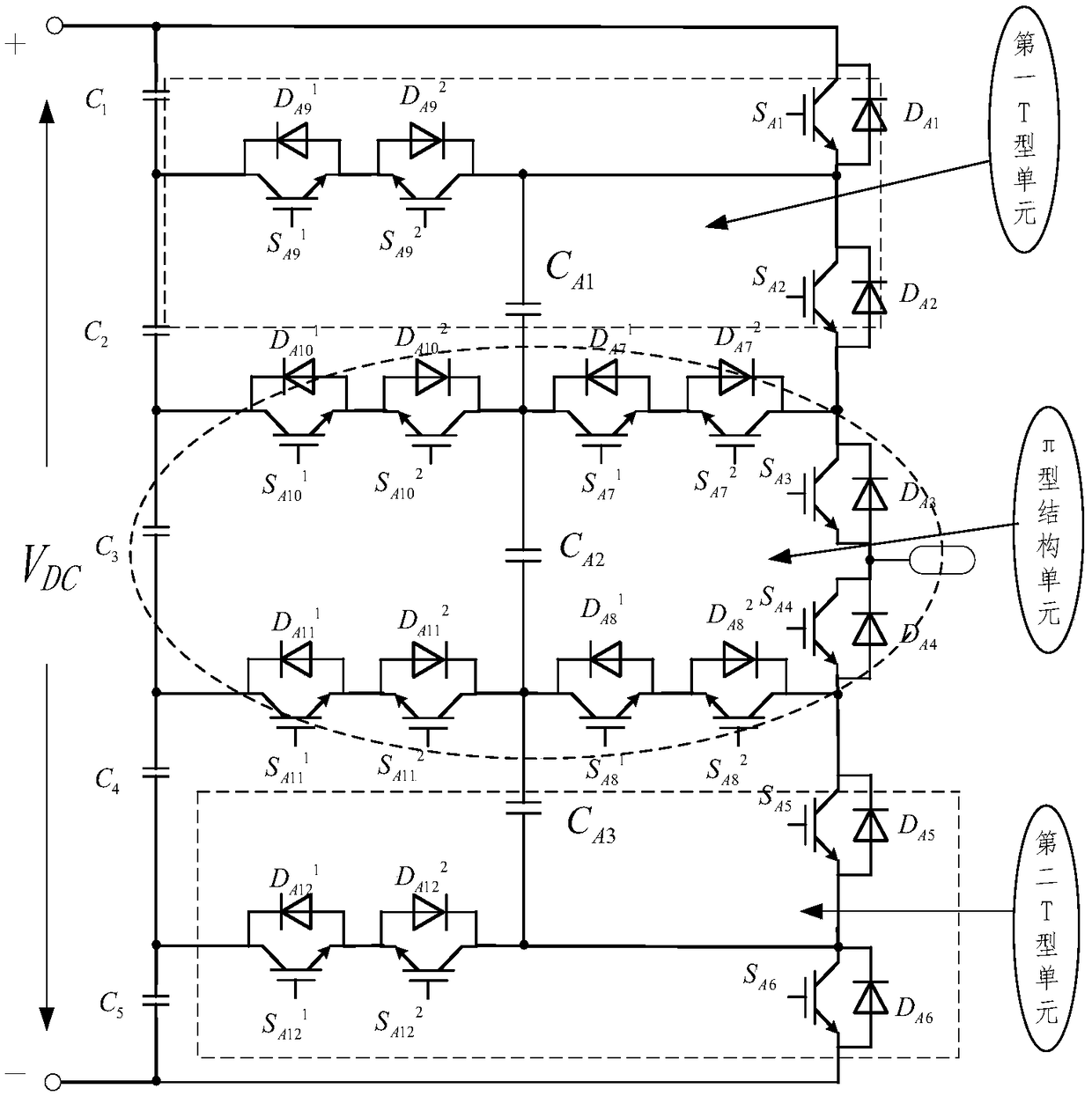
[0119] The present invention is a six-level circuit topology for power conversion systems, such as figure 2 As shown, it includes eighteen switching tubes S A1 ~S A6 , S A7 1 ~S A7 2 , S A8 1 ~S A8 2 , S A9 1 ~S A9 2 , S A10 1 ~S A10 2 , S A11 1 ~S A11 2 , S A12 1 ~S A12 2 , five bus capacitors C 1 ~C 5 and three clamping capacitors C A1 ~C A3 .

[0120] Among the eighteen switching tubes, four switching tubes are connected to form a first T-shaped unit, four switching tubes are connected to form a second T-shaped unit, and ten switching tubes are connected to form a π-shaped unit.

[0121] After the first to fifth bus capacitors are connected in series in the same direction, they are connected in parallel to the DC bus as a whole. There is a clamp capacitor between the T-shaped unit and the π-shaped structural unit, and the T-shaped unit and the π-shaped structural unit are connected in parallel on the DC bus as a whole.

[0122] The first swit...

Embodiment 3

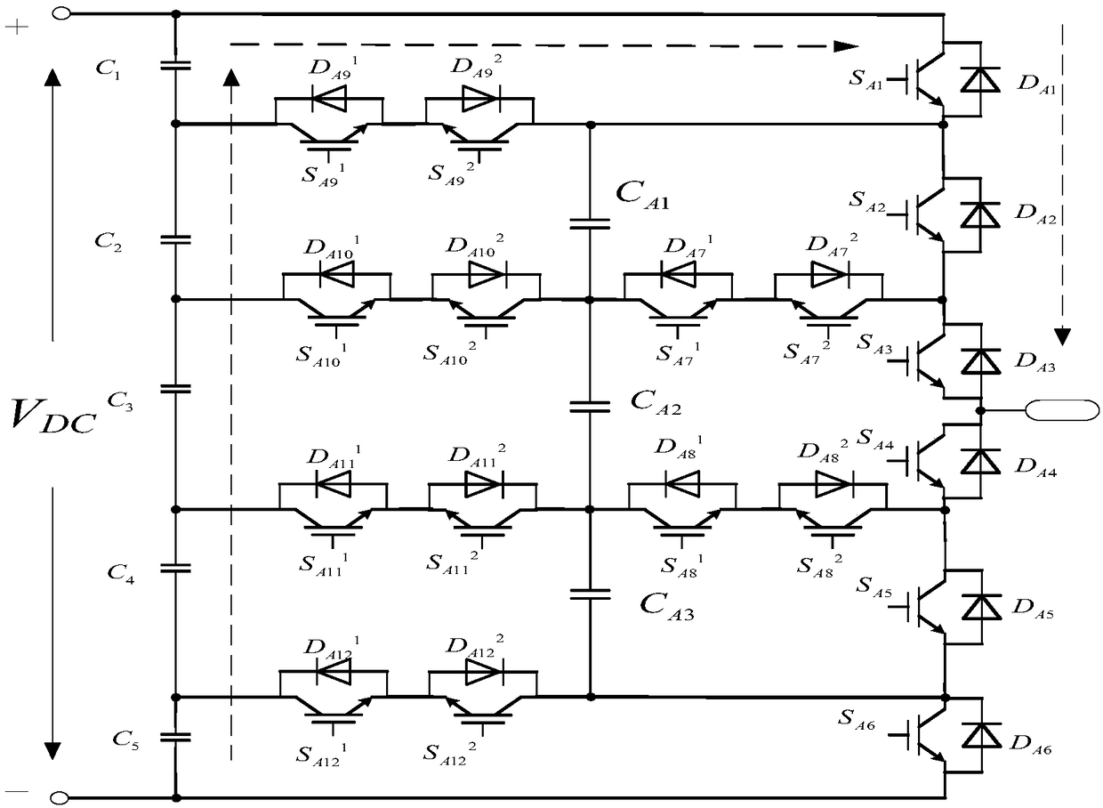
[0143] according to figure 2 A single-phase six-level inverter with the topology shown, including five bus capacitors C 1 ~C 5 , eighteen switching tubes S A1 ~S A6 , S A7 1 ~S A72 , S A8 1 ~S A8 2 , S A9 1 ~S A9 2 , S A10 1 ~S A10 2 , S A11 1 ~S A11 2 , S A12 1 ~S A12 2 , three clamping capacitors C A1 、C A2 、C A3 .

[0144] Among them, the first to fifth bus capacitors C 1 ~C 5 are the five capacitors on the DC bus, which are respectively one-fifth of the bus voltage, and the switching tube S of the whole system A1 ~S A6 , S A7 1 ~S A7 2 , S A8 1 ~S A8 2 , S A9 1 ~S A9 2 , S A10 1 ~S A10 2 , S A11 1 ~S A11 2 , S A12 1 ~S A12 2 Both anti-parallel diodes.

[0145] 12 switching tubes S A7 1 ~S A7 2 , S A8 1 ~S A8 2 , S A9 1 ~S A9 2 , S A10 1 ~S A10 2 , S A11 1 ~S A11 2 , S A12 1 ~S A12 2 Six pairs of switching tube groups composed of two pairs. The turn-on and turn-off signals given by each switc...


PUM


Abstract

The invention relates to a six-level circuit topology for a power conversion system, the circuit comprises a left circuit composed of first to fifth busbar capacitors connected in series in the same direction in turn, A first switching device A1, second switching device A2, third switching device A3, fourth switching device A4, fifth switching device A5, the sixth switching device A6 is sequentially connected in series on the right side, a first intermediate circuit composed of a ninth switching device A9, a second intermediate circuit composed of a seventh switching device A7 and a tenth switching device A10 in series, a third intermediate circuit composed of an eighth switching device A8 and an eleventh switching device A11 in series, a fourth intermediate circuit composed of a twelfth switching device A12, and three clamping capacitors. The invention can effectively reduce switching loss and voltage harmonics in the circuit, and can also control flexibly in controlling the switchingtransistor, and can be applied to power conversion devices such as inverters.

Description

technical field [0001] The invention relates to the technical field of power electronics, in particular to a six-level circuit topology used in a power conversion system. Background technique [0002] With the development of high-power power conversion, more and more occasions pay more attention to the application of multi-level circuit structure with high level and low harmonics. Multi-level high-power power conversion system can be used for wind power generation, photovoltaic inverter and other fields. However, in high-power applications, how to reduce loss, improve efficiency, and reduce output waveform harmonics are issues that system designers need to consider. [0003] The development and application of multi-level technology can effectively reduce the harmonics of the output voltage, making the output sinusoidal voltage waveform smoother. In multi-level circuits, the withstand voltage requirements for power switch tubes are reduced, which is of positive significance...

Claims


Application Information

Patent Timeline
IPC IPC(8): H02M7/483H02M1/12
CPCH02M1/12H02M7/483H02M1/0054Y02B70/10
Inventor 宋崇辉宋家祥韩涛刁乃哲孙先瑞王堃马羽
Owner NORTHEASTERN UNIV
Why Eureka
Try Eureka