A street lamp intelligent monitor and a monitoring method thereof
A monitor and street lamp technology, applied in energy-saving control technology, lamp circuit layout, lighting devices, etc., can solve the problems of street lamp opening and closing time misalignment, non-repeatability, error-prone, etc., so as to report accurate information in time and improve the accuracy of judgment. performance, saving labor costs
- Summary
- Abstract
- Description
- Claims
- Application Information
AI Technical Summary
Problems solved by technology
Method used
Image
Examples
Embodiment 1
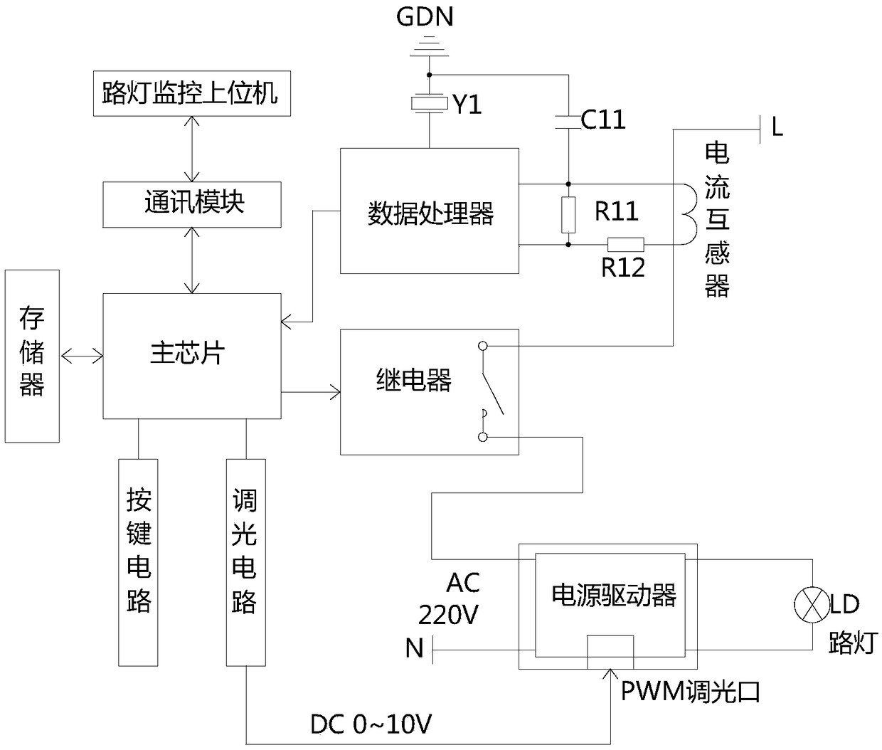
[0052] Embodiment 1: refer to Figure 1-7 ;
[0053] An intelligent street lamp monitor, comprising a street lamp monitoring host computer, a main chip, and a power supply module electrically connected to the main chip, a learning circuit, a GPRS communication module, a GPS positioning module, a dimming circuit, a memory, a voltage sampling circuit, and a current sampling circuit, leakage current sampling circuit, alarm signal circuit;
[0054] The GPRS communication module is used to receive and send data from the main chip; the street lamp monitoring host computer communicates with the main chip through the GPRS communication module;
[0055]Learning circuit: It is used to learn the current current or power parameters when the street lamp is normally illuminated, and send the measurement data to the main chip; the learning circuit includes a data processor, a relay, a current transformer, the neutral terminal of the street lamp power supply and the live wire of the street l...
Embodiment 2
[0062] Embodiment 2: refer to figure 1 , Figure 7 ;
[0063] The learning circuit also includes setting a certain percentage of the current overrun reference value. The current overrun reference value is the current average value of the current current learning period multiplied by the set learning current percentage. The current learning percentage is generally 150%. ~200% arbitrary adjustment, if it exceeds the reference value of the current limit, the current is considered to be over limit, and it is suspected of a ground fault or power theft, and the current over limit fault information is reported.
Embodiment 3
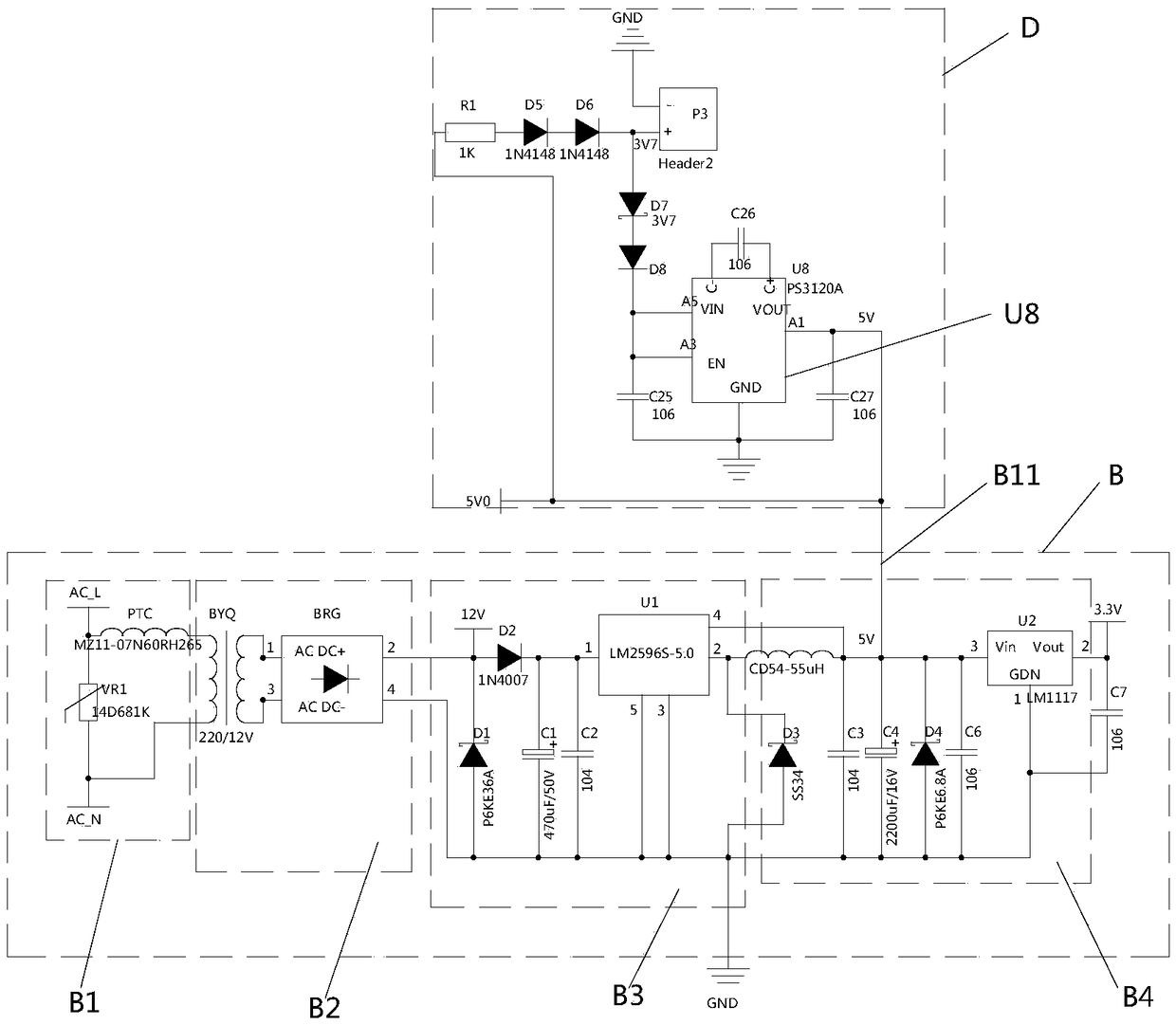
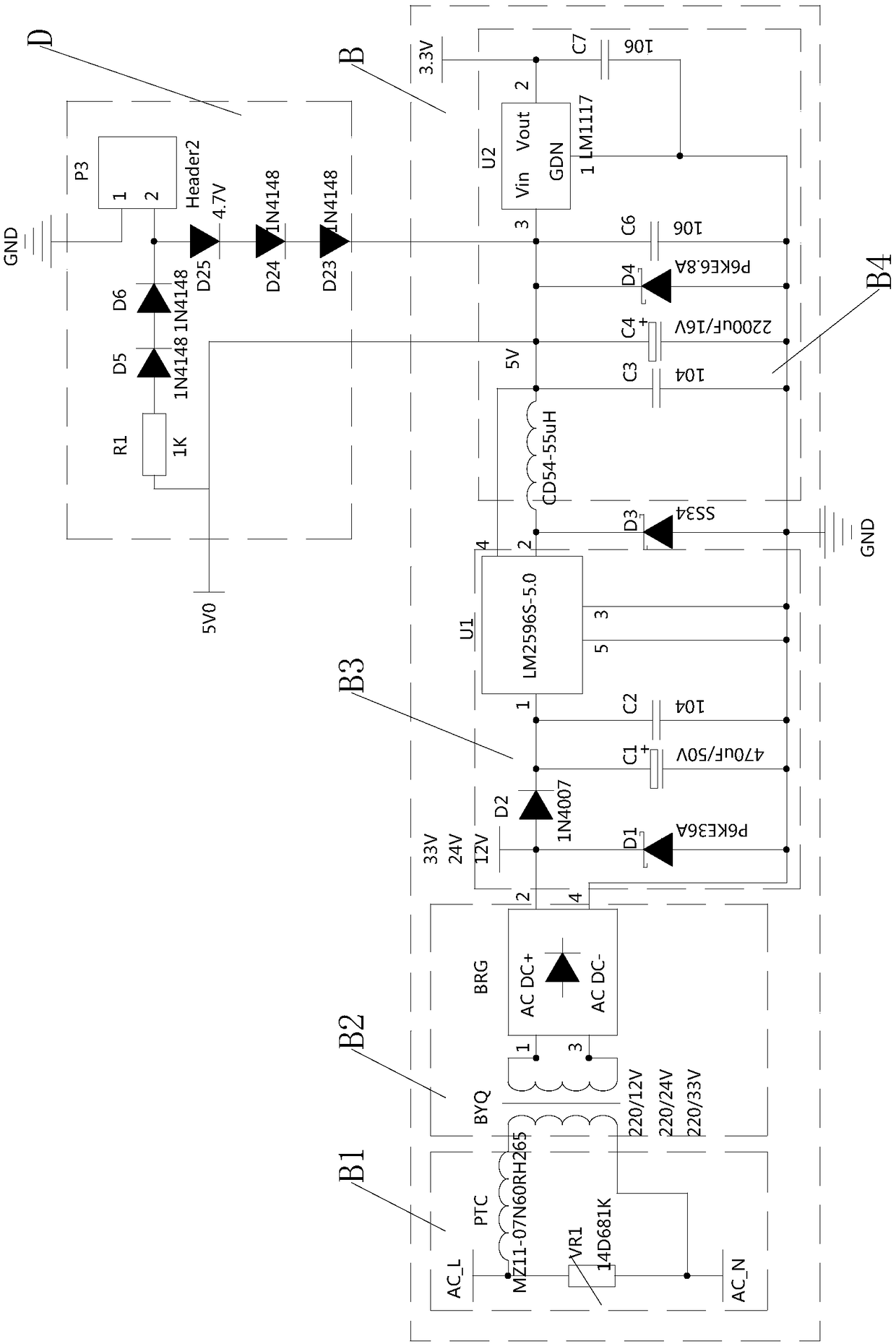
[0064] Embodiment 3: refer to figure 2 , image 3 , Figure 4 , Figure 7 ;
[0065] The power module includes a main charging power circuit B and a backup power circuit D;
[0066] Main charging power supply circuit B: it is used to charge the backup power supply circuit D and supply power to the main chip, communication module, and GPS positioning module;
[0067] Backup power circuit D: it is used to supply power to the main chip, communication module, and GPS positioning module when the main charging power circuit cannot provide power;
[0068] Backup power supply circuit D: (Scheme 1) The backup power supply circuit D includes a current-limiting resistor R1, two diodes D6, a backup power supply P3, a voltage regulator diode D7, a one-way conduction diode D8, and a first boost chip U8; the main charging power supply circuit The output terminal B1 of B is connected in series with two diodes D6 through the current-limiting resistor R1 and connected to the positive pole...
PUM
 Abstract
Description
Claims
Application Information
 - R&D
- Intellectual Property
- Life Sciences
- Materials
- Tech Scout
- Unparalleled Data Quality
- Higher Quality Content
- 60% Fewer Hallucinations
Browse by: Latest US Patents, China's latest patents, Technical Efficacy Thesaurus, Application Domain, Technology Topic, Popular Technical Reports.
© 2025 PatSnap. All rights reserved.Legal|Privacy policy|Modern Slavery Act Transparency Statement|Sitemap|About US| Contact US: help@patsnap.com


