A Plasma Contactor with Annular Ionization Chamber

A plasma and ionization chamber technology, applied in the direction of plasma, electrical components, etc., can solve the problem of high cost of transplantation, and achieve the effect of improving the total discharge efficiency, realizing the discharge capacity, and optimizing the emission characteristics

Active Publication Date: 2019-11-15
BEIJING INSTITUTE OF TECHNOLOGYGY
View PDF7 Cites 0 Cited by
  • Summary
  • Abstract
  • Description
  • Claims
  • Application Information

AI Technical Summary

Problems solved by technology

[0004] The purpose of the present invention is to provide a plasma contactor with a ring-shaped ionization chamber in order to solve the problem of high transplantation costs in different applications of the plasma contactor in the prior art

Method used


Image

  • A Plasma Contactor with Annular Ionization Chamber
  • A Plasma Contactor with Annular Ionization Chamber

Examples


Embodiment 1

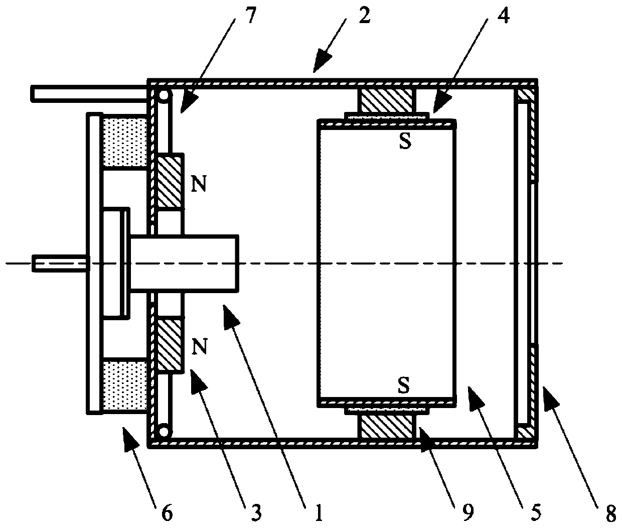
[0027] A plasma contactor with an annular ionization chamber, comprising: a hollow cathode plasma contactor, an ionization chamber housing, a first permanent magnet, a second permanent magnet, mica sheets, an anode housing and an ionization chamber housing insulating ceramics;

[0028] Connection relationship: the ionization chamber shell is a hollow cylinder structure with an open bottom end, and a through hole is opened at the top center of the cylinder; the flange of the hollow cathode plasma contactor is fixed to the ionization chamber shell through the insulating ceramics of the ionization chamber shell Connection; the first permanent magnet and the second permanent magnet are ring structures; the N pole of the first permanent magnet faces the interior of the ionization chamber; the S pole of the second permanent magnet faces the interior of the ionization chamber; the first permanent magnet is fixedly installed on the ionization chamber shell body top inner wall; the seco...

Embodiment 2

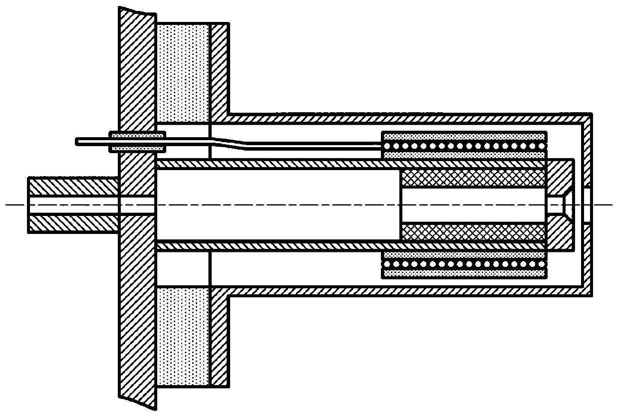
[0034] A plasma contactor with an annular ionization chamber, comprising: a hollow cathode plasma contactor, an ionization chamber casing, a first permanent magnet, a second permanent magnet, a mica sheet, an anode casing, an ionization chamber casing insulating ceramics, Secondary air supply pipeline;

[0035] Connection relationship: the ionization chamber shell is a hollow cylinder structure with an open bottom end, and a through hole is opened at the top center of the cylinder; the flange of the hollow cathode plasma contactor is fixed to the ionization chamber shell through the insulating ceramics of the ionization chamber shell Connection; the first permanent magnet and the second permanent magnet are ring structures; the N pole of the first permanent magnet faces the interior of the ionization chamber; the S pole of the second permanent magnet faces the interior of the ionization chamber; the first permanent magnet is fixedly installed on the ionization chamber shell bo...


PUM


Abstract

The invention relates to a plasma contactor, in particular to a plasma contactor combined with a hollow cathode electron generator and an annular ionization chamber, belonging to the field of gas discharge equipment. The ionization chamber is provided with a through hole at the center of the top end of the ionization chamber shell; The flange of the hollow cathode plasma contactor is fixedly connected with the shell of the ionization chamber through an insulating ceramic of the shell of the ionization chamber; A first permanent magnet is fixedly mounted on the inner wall of the top end of theionization chamber housing. A second permanent magnet is fixedly installed on the inner cylinder wall of the ionization chamber shell. The anode shell is an open hollow cylinder; The cylinder wall ofthe anode shell is fixedly connected with the mica sheet; The mica sheet is fixedly connected with the second permanent magnet; The invention can optimize the emission characteristics and reduce the transplant cost under different application situations. Under the same working condition, the potential difference can be reduced by about 40%.

Description

technical field [0001] The invention relates to a plasma contactor, in particular to a plasma contactor combining a hollow cathode electron generator and an annular ionization chamber, and belongs to the field of gas discharge equipment. Background technique [0002] The plasma contactor can inject plasma to the external environment, thereby realizing the physical process of charge exchange with the external environment, and its working external environment is generally a space environment. The emission characteristic is an important index to measure the working performance of the plasma contactor, which is the relationship between the potential difference of the cathode of the contactor relative to the external environment and the current of the emitted electrons. The application of plasma contactor puts forward strict requirements on its emission characteristics, that is, the potential difference under the rated emission current must be less than the required value. In or...

Claims


Application Information

Patent Timeline
Patent Type & Authority Patents(China)
IPC IPC(8): H05H1/24
CPCH05H1/24
Inventor 夏启蒙谢侃王宁飞张尊白松
Owner BEIJING INSTITUTE OF TECHNOLOGYGY
Why Eureka
Try Eureka