A stirrer for microbe fermentation

A microbial fermentation and stirring device technology, applied in the biological field, can solve the problems of small stirring range, insufficient and uniform stirring, etc., and achieve the effect of increasing the stirring range, ingenious structure, and improving stirring efficiency

Inactive Publication Date: 2018-12-14
ZHENGZHOU LIFUAI BIOLOGICAL TECH CO LTD
View PDF0 Cites 14 Cited by
  • Summary
  • Abstract
  • Description
  • Claims
  • Application Information

AI Technical Summary

Problems solved by technology

[0003] At present, in the research and development process of biotechnology products, the microbial fermentation raw materials are often stirred and mixed, but the stirring range of the current stirring device is small, especially the stirring blade only stirs the microbial fermentation raw materials at a fixed height position. Not sufficiently uniform, for this reason, a stirring device for microbial fermentation is now provided

Method used


Image

  • A stirrer for microbe fermentation
  • A stirrer for microbe fermentation
  • A stirrer for microbe fermentation

Examples


Embodiment 1

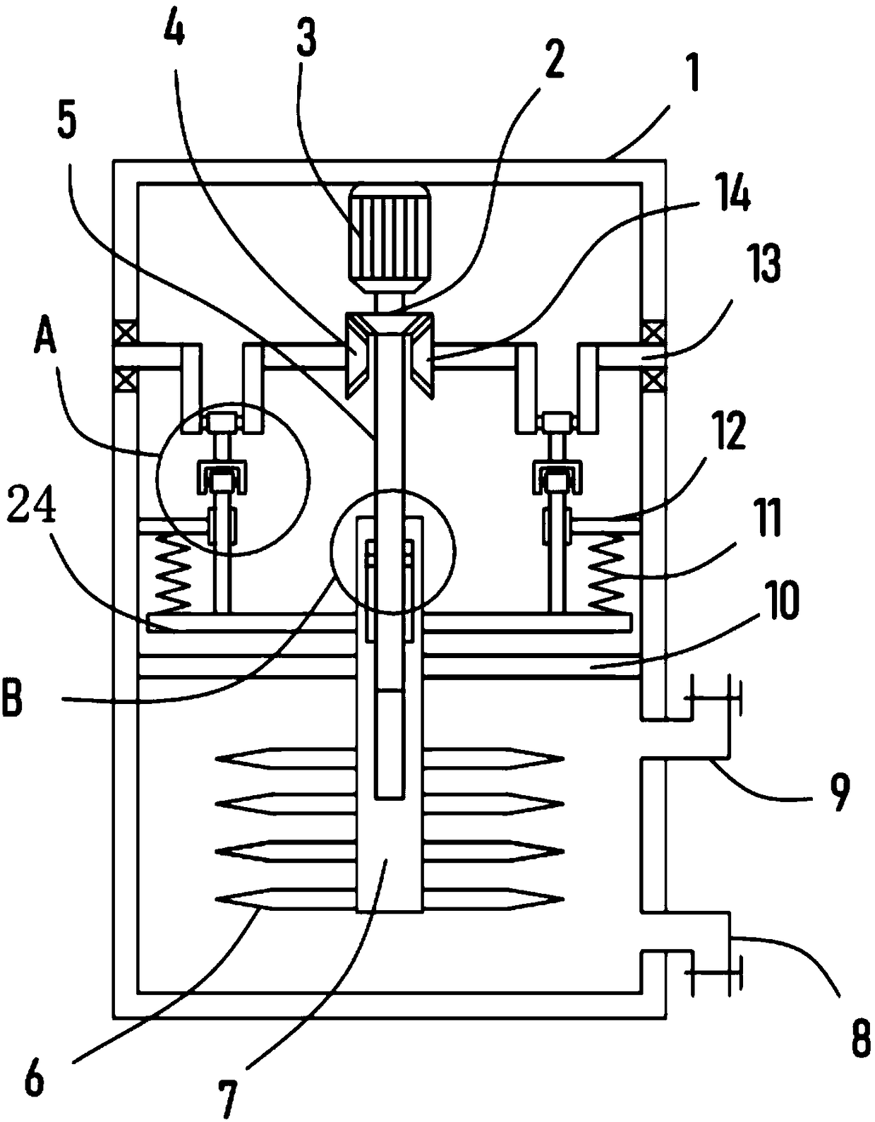
[0022] see Figure 1-4 A stirring device for microbial fermentation, comprising a box body 1, a partition plate 10 is horizontally and fixedly installed in the box body 1, the partition plate 10 divides the box body 1 into upper and lower parts, and the part below the partition plate 10 is used to contain microorganisms Fermentation raw materials, further, the feed pipe 9 and the discharge pipe 8 are installed on the box body 1, the microbial fermentation raw material can be injected into the box body 1 through the feed pipe 9, and the microbial fermentation after stirring can be discharged through the discharge pipe 8 raw material.

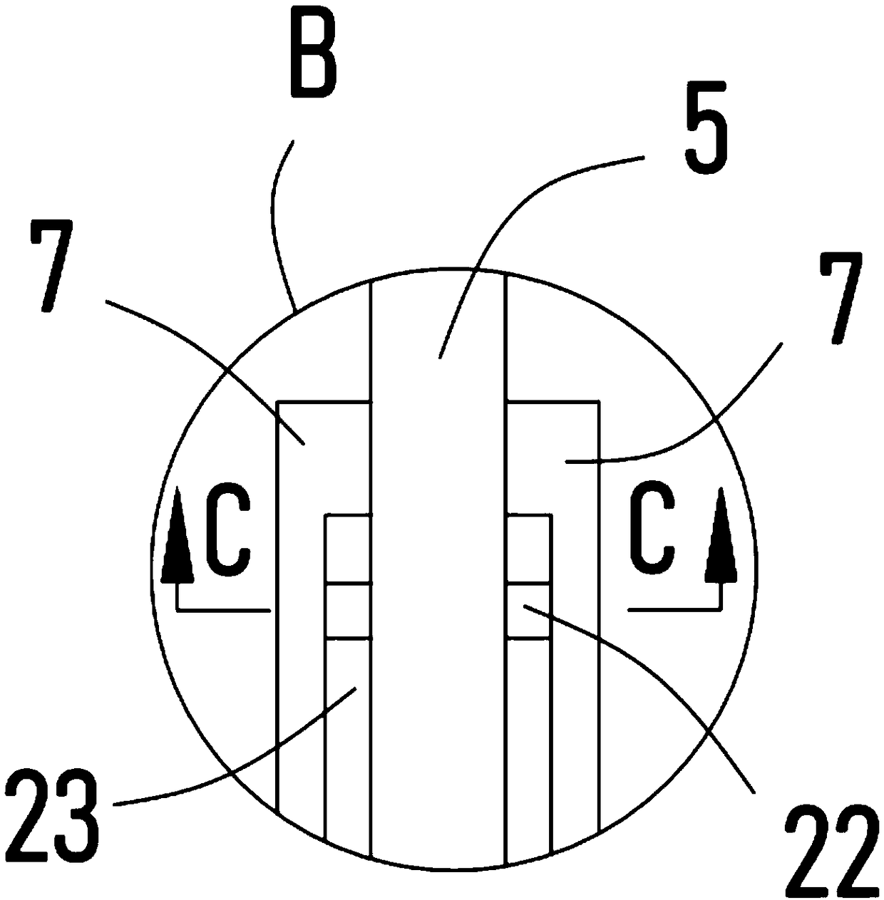
[0023] A driving motor 3 is fixedly installed in the box body 1, and the output shaft of the driving motor 3 is coaxially fixedly installed with a vertically arranged driving shaft 5, and the driving shaft 5 is covered with a stirring sleeve 7 that is slidably connected with the partition plate 10. A plurality of stirring blades 6 are evenly and...

Embodiment 2

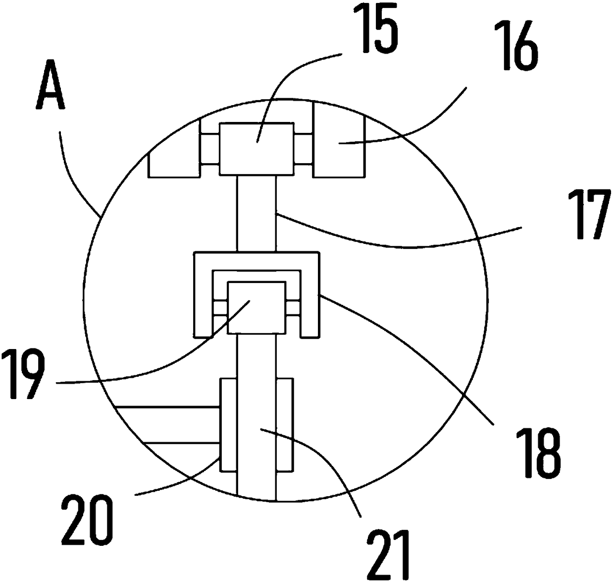
[0027] On the basis of Embodiment 1, in addition, two driven shafts 13 are rotatably arranged in the box body 1, and the driven bevel gears meshingly connected with the driving bevel gear 2 are respectively sleeved and fixedly installed on the two driven shafts 13. I4 and driven bevel gear II14.

[0028] Further, a crankshaft 16 is fixedly installed on the driven shaft 13, a collar 15 is sleeved on the crankshaft 16, a connecting rod 17 is fixedly installed on the collar 15, an n-shaped frame 18 is fixed on the bottom of the connecting rod 17, and an n-shaped frame 18 A connecting block 19 is hinged on the top, and a slide bar 21 is vertically fixedly installed at the lower end of the connecting block 19 , and a transmission plate 24 abutting against the lower end of the slide bar 21 is fixed horizontally on the side wall of the stirring sleeve 7 .

[0029] The driving bevel gear 2 is driven by the driving shaft 5, and then drives the driven bevel gear I4 and the driven bevel ...


PUM


Abstract

The invention provides a stirrer for microbe fermentation, and relates to the technical field of biology. The stirrer includes a tank body in which a separating plate is horizontally fixedly mounted.A drive motor is fixedly mounted in the tank body. A drive shaft vertically disposed is fixedly coaxially mounted to the output shaft of the drive motor, and is sleeved with a stirring sleeve slidingly connected to the separating plate. The surface of the stirring sleeve is evenly and fixedly provided with a plurality of stirring blades. A drive bevel gear is fixedly mounted to and sleeves the surface of the drive shaft. The stirrer is ingenious in structure and reasonable in design. A microbe fermentation raw material in the tank body can be rotated and stirred through rotation of the stirring blades, the stirring sleeve reciprocates up and down under the function of up-down reciprocation of a slide bar so as to drive the vertical positions of the stirring blades to change continuously, and the stirring blades can stir the microbe fermentation raw material of different heights in the tank body, thus greatly increasing the stirring range and effectively increasing the stirring efficiency.

Description

technical field [0001] The invention relates to the field of biotechnology, in particular to a stirring device for microbial fermentation. Background technique [0002] Biotechnology is a technology that applies the basic principles of biology, chemistry and engineering to use organisms or their components to produce useful substances or provide certain services to humans. In recent years, with the rapid development of modern biotechnology, including the achievements of genetic engineering, cell engineering, protein engineering, enzyme engineering and biochemical engineering, the use of biotransformation characteristics to produce chemical products, especially those that are difficult to obtain by general chemical means New products, changing existing processes, and solving the two thorny problems of energy crisis and environmental pollution, which have been plagued for a long time, have attracted more and more people's attention, and some have been put into reality. [000...

Claims


Application Information

Patent Timeline
Patent Type & Authority Applications(China)
IPC IPC(8): C12M1/02C12M1/00
CPCC12M23/34C12M23/48C12M27/02
Inventor 张健健
Owner ZHENGZHOU LIFUAI BIOLOGICAL TECH CO LTD
Why Eureka
Try Eureka