Electrolytic copper foil penetration point and pinhole detection equipment
A technology of electrolytic copper foil and testing equipment, which is applied in the field of electrolytic copper foil and can solve problems such as inability to detect copper foil
- Summary
- Abstract
- Description
- Claims
- Application Information
AI Technical Summary
Problems solved by technology
Method used
Image
Examples
Embodiment 1
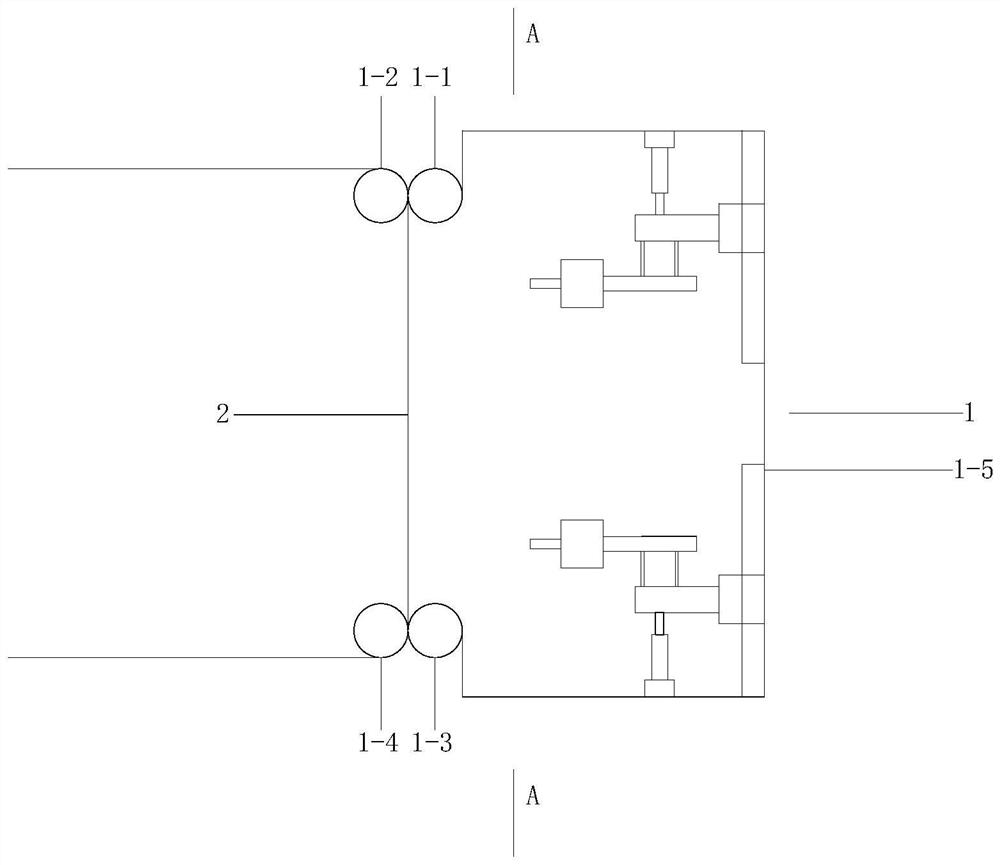
[0083]Embodiment 1: The detection equipment for the penetration point and pinhole of the electrolytic copper foil includes: an atomization system 1 and a copper foil 2 .
[0084] Atomization system 1 includes: atomization system frame, top guide roller 1-1, top drive roller 1-2, bottom guide roller 1-3, bottom drive roller 1-4, housing 1-5; top guide roller 1- 1. The top drive roller 1-2, the bottom guide roller 1-3, the bottom drive roller 1-4, and the housing 1-5 are all fixed on the frame of the atomization system;
[0085] The top guide roller 1-1, the top drive roller 1-2, the bottom guide roller 1-3, and the bottom drive roller 1-4 are arranged horizontally;
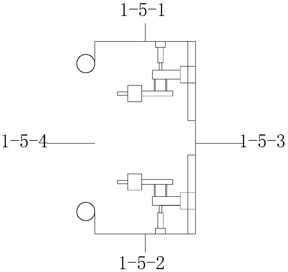
[0086] The shell includes: an upper plate 1-5-1, a lower plate 1-5-2, and a side wall plate 1-5-3, and an opening 1-5-4 is arranged on the side wall plate; the shell can be a cuboid or cylinder;
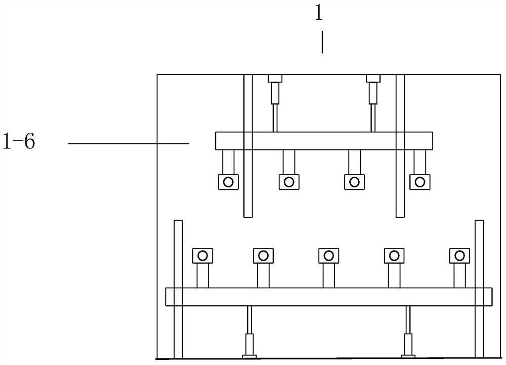
[0087] Also includes: the first mobile spray system 1-6, the second mobile spray system 1-7, the first mobile spray s...
Embodiment 2
[0120] Embodiment two: the bottom guide roller 1-3, the bottom driving roller 1-4 in the embodiment one, the copper foil passes through the extrusion of both the bottom guiding roller 1-3 and the bottom driving roller 1-4, so that the dilute sulfuric acid solution is subjected to After squeezing, it can enter the penetration points and pinholes more fully.
[0121] However, the first embodiment has the following difference. When the equipment is running for a long time, more solution will accumulate at the bottom of the atomization system 1, especially at the bottom guide rollers 1-3 and bottom driving rollers 1-4. The purpose of the second embodiment is to solve the above problems.
[0122] The difference from Embodiment 1 is that: the bottom guide roller 1-3 and the bottom driving roller 1-4 are cancelled. The lower plate of the housing of the atomization system 1 is provided with an L-shaped plate body 1-8, and a third telescopic power mechanism 1-9 is fixed on the vertica...
Embodiment 3
[0125] Embodiment three: on the basis of embodiment two, further improvement. The bottom guide roller 1-3 and the bottom drive roller 1-4 are arranged under the housing 1-5, that is, the copper foil first passes through the rubber block 1-10 and the vertical support 3 to initially remove moisture, and then passes through the bottom guide roller 1- 3. The bottom drive rollers 1-4 make the copper foil run from vertical to horizontal, so that dilute sulfuric acid solution can enter the penetration point and pinhole; finally, the fourth telescopic power is installed on the lower surface of the lower plate of the shell mechanism, the other end of the fourth telescopic power mechanism is connected with a pressing plate, and the surface of the pressing plate is provided with a plurality of pressing rubber blocks at intervals, and the width of the rubber blocks is the same as that of the copper foil.
[0126] The method of embodiment 3 is that after the copper foil is sprayed, the sol...
PUM
 Abstract
Description
Claims
Application Information
 - R&D
- Intellectual Property
- Life Sciences
- Materials
- Tech Scout
- Unparalleled Data Quality
- Higher Quality Content
- 60% Fewer Hallucinations
Browse by: Latest US Patents, China's latest patents, Technical Efficacy Thesaurus, Application Domain, Technology Topic, Popular Technical Reports.
© 2025 PatSnap. All rights reserved.Legal|Privacy policy|Modern Slavery Act Transparency Statement|Sitemap|About US| Contact US: help@patsnap.com


