Radio-frequency device test probe with built-in inductor

A technology of radio frequency devices and test probes, which is applied to components, instruments, and measuring electronics of electrical measuring instruments, can solve problems such as test fluctuations, signal delays, and low accuracy, and achieve the elimination of test errors and volatility, and eliminate Distortion of signal transmission, effect of improving accuracy

Pending Publication Date: 2018-12-14
HUAIYIN TEACHERS COLLEGE
View PDF10 Cites 3 Cited by
  • Summary
  • Abstract
  • Description
  • Claims
  • Application Information

AI Technical Summary

Problems solved by technology

In the production and research of radio frequency devices, people in the industry know that radio frequency devices are sensitive to the test system. Therefore, the test results of radio frequency filters are highly volatile and have low accuracy.
The inaccuracy of its test results will cause great economic losses to manufacturers, and will also have a negative impact on scientific research results
[0003] The test results of RF filters have large fluctuations and low precision, which makes the accuracy of the test results poor. The main reasons are found in the following aspects: First, the performance difference of the network analyzer. Regular calibration checks and maintenance will also cause test fluctuations
The second is the signal delay caused by different cables. At present, the calibration of test equipment often cannot calibrate the cables; at the same time, the replacement and removal of cables during the test will also cause large test fluctuations.
The third is that for different products, customers will request to add inductance or capacitance components to some ports of the product for matching when using the product, and in the batch test process, the manufacturer will choose to test through the matching strategy at the software level. In order to improve production efficiency; however, the negative impact of this operation is that the test results may be quite different from the real performance of the product

Method used


Image

  • Radio-frequency device test probe with built-in inductor
  • Radio-frequency device test probe with built-in inductor

Examples


Embodiment Construction

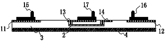
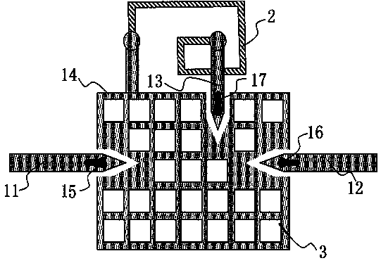
[0022] Such as Figure 1-2 As shown, a radio frequency device test probe with embedded inductance includes: a substrate metal layer 4, which is the supporting metal layer of the entire test fixture; an insulating layer arranged on the substrate metal layer 4 upper side Layer 3, the top of the insulating layer 3 is distributed and fixed with the first metal layer 1; the first metal layer 1 includes the first metal 11, the second metal 12, the third metal 13 and the fourth metal 14; The above-mentioned first metal 11 and second metal 12 are respectively arranged on both sides of the top of the insulating layer 1 ; the third metal 13 and fourth metal 14 are arranged in the middle of the top of the insulating layer 3 .

[0023] One end of the upper surface of the first metal 11 is fixedly connected with a first probe 15, and the first probe 15 is used as the signal output end of the whole test fixture, and is connected with the signal input end of the radio frequency device under ...


PUM


Abstract

The invention discloses a radio-frequency device test probe with a built-in inductor. The radio-frequency device test probe with the built-in inductor comprises a substrate metal layer and an insulation layer; the insulation layer is arranged at the upper side of the substrate metal layer; a first metal layer is arranged on the top of the insulation layer at intervals; the first metal layer comprises first metal, second metal, third metal and fourth metal; the first metal, the second metal and the third metal are separately connected to metal probes; the metal probes are separately connected with the signal input end, the signal output end and the grounding end of a radio-frequency device to be tested; the other ends of the first metal and the second metal are connected with the signal output end of a network analyzer through a cable; the other end of the third metal is connected to the second metal layer, so that a bipolar inductor is formed; the other end of the second metal layer isconnected with one end of the fourth metal; and the other end of the fourth metal is grounded. According to the radio-frequency device test probe with the built-in inductor in the invention, the testerror and the fluctuation performance due to the cable and the network analyzer can be eliminated; the test precision is improved; and the test accuracy is improved.

Description

technical field [0001] The invention belongs to the field of radio frequency device testing, and in particular relates to a radio frequency device test probe with embedded inductance. Background technique [0002] With the advent of the 5G era and the rapid development of radio frequency communication technology, radio frequency filters have been highly valued by the industry. In the production and research of radio frequency devices, people in the industry know that radio frequency devices are sensitive to the test system. Therefore, the test results of radio frequency filters are highly volatile and have low accuracy. The inaccuracy of the test results will cause great economic losses to the manufacturers, and will also have a negative impact on the results of scientific research. [0003] The test results of RF filters have large fluctuations and low precision, which makes the accuracy of the test results poor. The main reasons are found in the following aspects: First, ...

Claims


Application Information

Patent Timeline
Patent Type & Authority Applications(China)
IPC IPC(8): G01R1/067
CPCG01R1/067
Inventor 任舰苏丽娜李文佳
Owner HUAIYIN TEACHERS COLLEGE
Why Eureka
Try Eureka