Method used for measuring photoetching machine vertical measuring system reflector surface shape

A reflective mirror surface and measurement system technology, which is applied in the direction of measuring devices, microlithography exposure equipment, optical devices, etc., can solve the problems of increasing the cost of the whole machine, achieve the effects of improving accuracy, eliminating test errors, and reducing costs

Active Publication Date: 2015-07-15
SHANGHAI MICRO ELECTRONICS EQUIP (GRP) CO LTD
View PDF6 Cites 2 Cited by
  • Summary
  • Abstract
  • Description
  • Claims
  • Application Information

AI Technical Summary

Problems solved by technology

However, this method requires the participation of multiple leveling and focusing sensors, which will increase the cost of the whole machine

Method used


Image

  • Method used for measuring photoetching machine vertical measuring system reflector surface shape
  • Method used for measuring photoetching machine vertical measuring system reflector surface shape
  • Method used for measuring photoetching machine vertical measuring system reflector surface shape

Examples


Embodiment Construction

[0031] Specific embodiments of the present invention will be described in detail below in conjunction with the accompanying drawings.

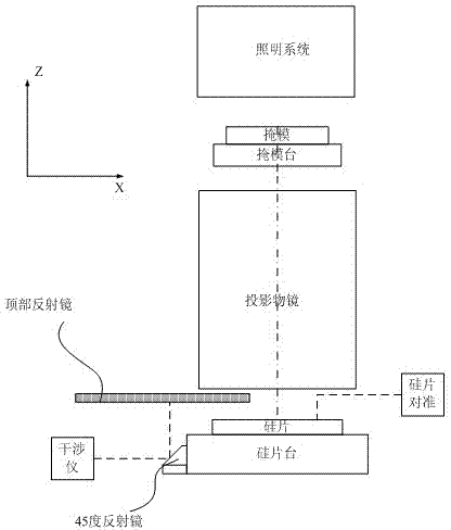
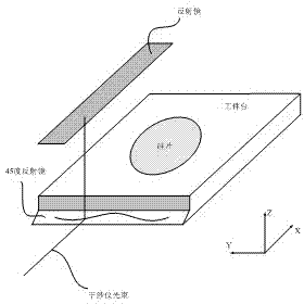
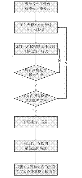
[0032] The present invention determines the optimum focal plane height through the method of FOCAL (Focus calibration using alignment procedure). FOCAL technology is a main technology used to detect the axial image quality parameters of lithography machines. In the FOCAL method, a specific FOCAL marker (such as Figure 4 ) are exposed at different defocus amounts, and then the alignment offset (Alignment Offset, AO) of the FOCAL mark exposed to the substrate is detected by the optical alignment system of the lithography machine. The Z-direction offset of the FOCAL marker is calculated using the detected alignment offset. Finally, the axial image quality parameters of the lithography machine, such as the best focal plane and astigmatism, are calculated by using the Z-direction offset of the FOCAL mark.

[0033] The invention is based on fig...


PUM


Abstract

The invention provides a method used for measuring photoetching machine vertical measuring system reflector surface shape. The method comprises following steps: 1) a substrate is uploaded onto a workpiece table, and a reticle mask with confirmable optimum focal plane marks is uploaded onto a reticle stage; 2) the Y direction position of the workpiece table is maintained to be unchanged, n times of stepping on the Z direction of the workpiece table are realized via controlling by an interferometer, wherein after each time of stepping of the workpiece table, stepping of a same space on the X direction is carried out, so that exposure of the confirmable optimum focal plane marks of the reticle mask onto the substrate is realized; 3) after n times of height exposure, stepping of one space of the workpiece table on the Y direction is realized, and the step 2) is repeated until exposure of the whole substrate is realized, and exposure of m groups of masks is realized; 4) the substrate is subjected to development and drying, and is uploaded onto the workpiece table, and reading of alignment positions of n*m masks is carried out; 5) alignment offset of the masks is calculated based on the alignment positions, the optimum focal position BF of yi at each Y-direction is obtained via calculation based on the relationship of the alignment positions with defocusing amount, so that changing amount of the optimum focal position is represented by a formula in the invention, and whererin F-T are used for representing the workpiece table positions; 6) fitting of the reflector surface shape is carried out based on the m positions yi, and distance <delta>hi of actual positions of the corresponding reflector surface shape to the nominal positions.

Description

[0001] technical field [0002] The invention relates to the technical field of semiconductor manufacturing, in particular to a method for measuring the mirror surface shape of a vertical measurement system of a lithography machine. Background technique [0003] With the improvement of the integration level of semiconductor integrated circuits, the feature size of integrated circuits is getting smaller and smaller. The feature size of the integrated circuit is ultimately determined by the optical projection device. As the feature size becomes smaller and smaller, the focal depth of the optical projection device is also smaller and smaller. Therefore, one of the key technologies to realize the high-precision photolithography process is to accurately control the upper surface of the silicon wafer to be within the focal depth range of the optical projection device. [0004] U.S. Patent US6208407B1 proposes a lithography machine device in which the vertical movement of a movin...

Claims


Application Information

Patent Timeline
IPC IPC(8): G03F7/20G01B11/24
Inventor 孙朋
Owner SHANGHAI MICRO ELECTRONICS EQUIP (GRP) CO LTD
Why Eureka
Try Eureka