
Improved level set topology optimization method for stable hole formation

A technology of topology optimization and level set, applied in design optimization/simulation, instrumentation, calculation, etc., can solve problems such as difficult numerical analysis, inability to generate holes, and dependence on initial design, etc., to achieve wide application range, easy understanding and implementation, and method simple effect

Active Publication Date: 2018-12-14
HUAZHONG UNIV OF SCI & TECH
View PDF1 Cites 7 Cited by
  • Summary
  • Abstract
  • Description
  • Claims
  • Application Information

AI Technical Summary

Problems solved by technology

[0004] In the traditional level set topology optimization method, due to the nature of the Hamilton-Jacobi equation, holes cannot be generated inside the structure
Therefore, the initial design of the structure in level set topology optimization needs to have many holes, which causes the method to depend on the initial design, especially for two-dimensional problems. In order to overcome the dependence on the initial design, the level set method has been improved a lot, such as Combining topological derivatives or using radial basis functions, but these improvements need to define many holes in the design domain in the initial design, and the position, number and size of the holes will have a great impact on the final optimization results; in addition, these The concept of improvement measures is complex, it is difficult to carry out numerical analysis, and it is difficult to apply in actual engineering. At present, there is no effective method for level set topology optimization to stably form holes and be feasible in engineering applications

Method used


Image

  • Improved level set topology optimization method for stable hole formation
  • Improved level set topology optimization method for stable hole formation
  • Improved level set topology optimization method for stable hole formation

Examples


Embodiment Construction

[0051] In order to make the object, technical solution and advantages of the present invention clearer, the present invention will be further described in detail below in conjunction with the accompanying drawings and embodiments. It should be understood that the specific embodiments described here are only used to explain the present invention, not to limit the present invention. In addition, the technical features involved in the various embodiments of the present invention described below can be combined with each other as long as they do not constitute a conflict with each other.

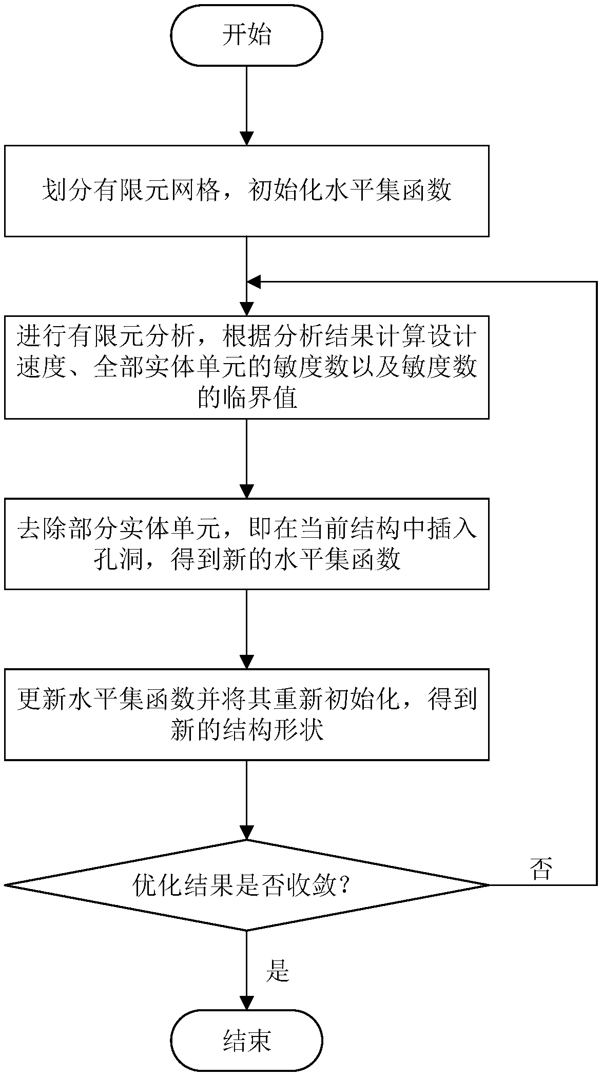
[0052] figure 1 is a flow chart of a method constructed according to a preferred embodiment of the present invention, such as figure 1 As shown, an improved level set topology optimization method for stable hole formation, the method includes the following steps:

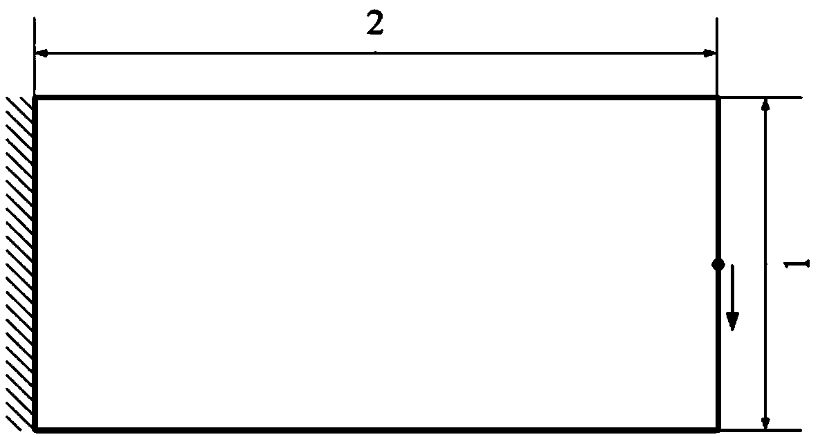
[0053] figure 2 is a structural schematic diagram of a planar cantilever beam to be optimized constructed according to a preferr...


PUM


Abstract

The invention belongs to the technical field of structural topology optimization, and discloses an improved level set topology optimization method for stable hole formation. The method includes: (a) dividing the finite element mesh into design domains, initially dividing the mesh into solid and cavity domains, and initially assigning values to the level set functions; (b) calculating a displacement vector in the design domain; (c) calculating the sensitivity of each grid cell in the velocity field and the physical region; (d) optimizing the initialized solid region, the cavity region and the level set function for the first time by using the sensitivity number; (e) using the velocity field to update the level set function of each grid cell in the entity and the cavity region respectively so as to redivide the entity region and the cavity region, thereby realizing the second optimization; (f) judging whether the result of the second optimization converges or not according to the flexibility and volume error. The invention overcomes the defect that the traditional level set topology optimization method cannot form holes in the structure, and solves the dependence of the optimizationproblem on the initial design, which is stable and effective.

Description

technical field [0001] The invention belongs to the technical field of structural topology optimization, and more specifically relates to an improved level set topology optimization method for stably forming holes. Background technique [0002] Structural topology optimization is a new digital structure design method. By establishing a mathematical model including design variables, objective functions and constraints, finite element analysis is performed on the structure, and in the design domain, iteratively obtains the results that satisfy the constraints according to optimization criteria or mathematical programming methods. Conditions and achieve the material layout of the design goals. Structural topology optimization has great application value in industries such as automobiles, aerospace, and high-end equipment. [0003] Level set topology optimization method and BESO (Bidirectional Progressive Structural Optimization) method are two commonly used methods in structur...

Claims


Application Information

Patent Timeline
Patent Type & Authority Applications(China)
IPC IPC(8): G06F17/50
CPCG06F30/23
Inventor 夏奇田野史铁林
Owner HUAZHONG UNIV OF SCI & TECH
Learn More